WHEELS AND TIRES
10 -
6
Front beam inspection
◆
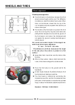
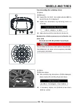
The front beam is the distance between the front
wheels at axle height and the rear. The difference
in distance is called the anterior beam value. When
there is A front beam, viewed from the top of the
car, the distance A (rear) is greater than B (front), as
shown in the fi gure.
◆
The function of the front beam is to prevent the front
wheel from running off at any time and reduce the
sliding friction between the tire and the ground. If
the front beam is not correct, the front wheels will
rub against the ground, causing tread damage or
abnormal wear.
The caster and camber angles of the kingpin are
built-in and di bit reqyure adjustment.
A
(
rear
)
– B
(
front
)
=toe value
(
The distances A and B are measured at the height
of the axle when the vehicle is parked on a flat
surface.
)
◆
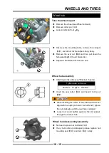
Apply thick chalk or paint line near the center of the
front tire.
◆
When turning a wheel, make a small mark near the
center of the chalk coating with a needle marker.
◆
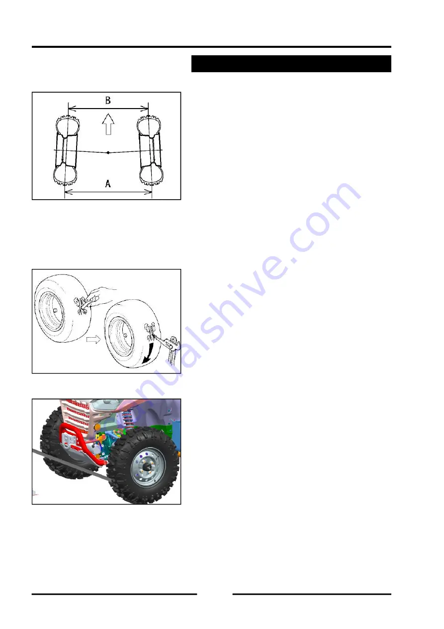
Place the front wheel on the ground and fix the
handlebars.
◆
At axle height, measure the distance between front
tire front and rear marking or paint line.
◆
The front beam is obtained by subtracting the
measured value at the rear from the measured value
at the front. If the forebeam is not within the specifi ed
range, continue the forebeam adjustment procedure.
Standard
:
10±10mm
(
0.39±0.39inch
)
Wheel alignment
Summary of Contents for SNARLER ATV 2021 Series
Page 1: ...SERVICE MANUAL ATV SERIES PRODUCTS 20210804 V01...
Page 39: ...ENGINE LUBRICATION SYSTEM ENGINE LUBRICATION SYSTEM 3 1 2 Exploded view...
Page 99: ...ENGINE COOLING SYSTEM ENGINE COOLING SYSTEM 3 4 2 Exploded view...
Page 120: ...ENGINE TOP END ENGINE TOP END 3 5 10 Spark Plug Valve Cover Throttle Body Camshaft...
Page 153: ...CVT SYSTEM CVT SYSTEM 3 6 2 L L G G G G R R Lh Lh R R R R Exploded view...
Page 155: ...CVT SYSTEM CVT SYSTEM 3 6 4 R R R R G G R R L L Lh Lh M M G G G G G G...
Page 185: ...4 13 FRONT AND REAR DIFFERENTIAL FRONT AND REAR DIFFERENTIAL...
Page 212: ...COOLING SYSTEM 6 6 Special tools and sealants Silicone Sealant...
Page 230: ...FRONT REAR SUSPENSION 9 2 Exploded view of Front suspension...
Page 232: ...FRONT REAR SUSPENSION 9 4 Exploded view of Rear suspension...
Page 249: ...WHEELS AND TIRES 10 5 Special Tools Jack...
Page 264: ...BRAKE SYSTEM 11 5 Inside Circlip Pliers Special tool...
Page 276: ...STEERING SYSTEM 12 2 Exploded View of Steering System 1 2 A A 3 4 5 5 5 6 3 B...
Page 323: ...ELECTRICAL SYSTEM 14 15 EFI system Schematic diagram of EFI system...
Page 383: ...ELECTRICAL SYSTEM 14 75 B10 B11 B12 B14 B15 B16...


