BRAKE SYSTEM
11 -
8
◆
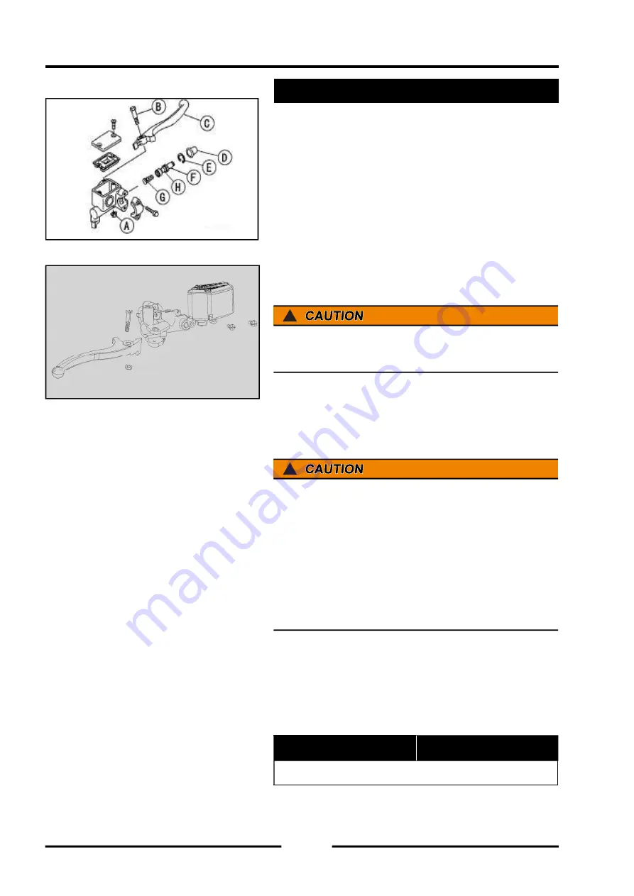
Remove
:
Master Cylinder (see Master Cylinder Removal)
【
A
】
Brake Lever Pivot Nut
【
B
】
Brake Lever Pivot Bolt
【
C
】
Brake Lever
【
D
】
Dust Cover
【
E
】
Circlip
【
F
】
Piston
【
G
】
Spring
!
Do not remove the secondary cup
【
H
】
from the piston
since removal will damage it.
Master Cylinder Assembly
◆
Before assembly, clean all parts including the master
cylinder with brake fl uid or alcohol.
!
Except for the disc pads and disc, use only disc brake
fluid, isopropyl alcohol, or ethyl alcohol for cleaning
brake parts. Do not use any other fluid for cleaning
these parts. Gasoline, engine oil, or any other petroleum
distillate will cause deterioration of the rubber parts. Oil
spilled on any part will be diffi cult to wash off completely,
and will eventually deteriorate the rubber used in the
disc brake.
◆
Take care not to scratch the piston or the inner wall
of the cylinder.
◆
Apply brake fluid to the removed parts and to the
inner wall of the cylinder.
◆
Tighten:
Torque - Brake Lever Pivot Bolt
Brake Lever Pivot Bolt Locknut
5.9 N·m
(
0.6kgf·m
,
70.8in·lb
)
Master Cylinder Inspection (Visual Inspection) •Refer to
the Brakes in the Periodic Maintenance chapter.
Master Cylinder Disassembly
Summary of Contents for SNARLER ATV 2021 Series
Page 1: ...SERVICE MANUAL ATV SERIES PRODUCTS 20210804 V01...
Page 39: ...ENGINE LUBRICATION SYSTEM ENGINE LUBRICATION SYSTEM 3 1 2 Exploded view...
Page 99: ...ENGINE COOLING SYSTEM ENGINE COOLING SYSTEM 3 4 2 Exploded view...
Page 120: ...ENGINE TOP END ENGINE TOP END 3 5 10 Spark Plug Valve Cover Throttle Body Camshaft...
Page 153: ...CVT SYSTEM CVT SYSTEM 3 6 2 L L G G G G R R Lh Lh R R R R Exploded view...
Page 155: ...CVT SYSTEM CVT SYSTEM 3 6 4 R R R R G G R R L L Lh Lh M M G G G G G G...
Page 185: ...4 13 FRONT AND REAR DIFFERENTIAL FRONT AND REAR DIFFERENTIAL...
Page 212: ...COOLING SYSTEM 6 6 Special tools and sealants Silicone Sealant...
Page 230: ...FRONT REAR SUSPENSION 9 2 Exploded view of Front suspension...
Page 232: ...FRONT REAR SUSPENSION 9 4 Exploded view of Rear suspension...
Page 249: ...WHEELS AND TIRES 10 5 Special Tools Jack...
Page 264: ...BRAKE SYSTEM 11 5 Inside Circlip Pliers Special tool...
Page 276: ...STEERING SYSTEM 12 2 Exploded View of Steering System 1 2 A A 3 4 5 5 5 6 3 B...
Page 323: ...ELECTRICAL SYSTEM 14 15 EFI system Schematic diagram of EFI system...
Page 383: ...ELECTRICAL SYSTEM 14 75 B10 B11 B12 B14 B15 B16...

