2 -
12
MAINTENANCE
MAINTENANCE
4. Vacuumize and refi ll front right brake hose
Refer to the procedures of vacuumizing front left brake
hose to vacuumize and refi ll front right brake hose.
5. Vacuumize and refi ll front brake hose
◆
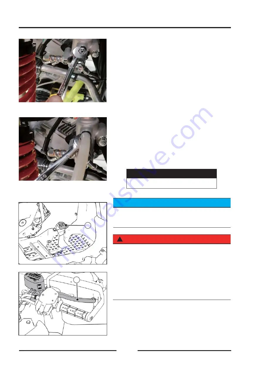
Open distribution valve dust cap and counter
clockwise open air inlet bolts of distribution valve.
.
◆
Connect one end of vacuum tank to air source and
the other end hose to air outlet.
◆
Counter clockwise rotate air valve hand shank to
open vacuum tank. Vacuumize pipelines of front
left and front right brakes respectively. Meanwhile,
check liquid level of rear brake cup and hand brake
main pump oil cup and refi ll in time. Refi ll only when
level is lower than MIN.
◆
In the vacuum process of all pipelines, refi ll oil cup
twice at least each time and screw up air nozzle
clockwise and then rotate vacuum tank air valve to
close it.
Torque of Air Outlet
7.9N·m
7.9N·m
(
(
0.8kgf·m
0.8kgf·m
,
,
94.8in·lb
94.8in·lb
)
)
TIPS
TIPS
Check liquid level in the brake oil cup regularly
Check liquid level in the brake oil cup regularly
and refi ll.
and refi ll.
Discharge air in the brake system
Discharge air in the pipeline when you replace or
reassemble brake parts
◆
Remove hand brake upper pump assembly oil cup
!
!
WARNING
WARNING
Step on brake pedal
Step on brake pedal
【
【
A
A
】
】
and hand grasp front brake
and hand grasp front brake
shank
shank
【
【
B
B
】
】
respectively. If you have soft or “sponge”
respectively. If you have soft or “sponge”
feeling, in this process, it means there is air in the brake
feeling, in this process, it means there is air in the brake
system. Please repeat above procedures to vacuumize
system. Please repeat above procedures to vacuumize
(discharge air) the pipeline until you have no such
(discharge air) the pipeline until you have no such
feeling.
feeling.
B
B
A
A
Summary of Contents for SNARLER ATV 2021 Series
Page 1: ...SERVICE MANUAL ATV SERIES PRODUCTS 20210804 V01...
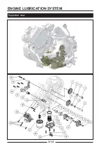
Page 39: ...ENGINE LUBRICATION SYSTEM ENGINE LUBRICATION SYSTEM 3 1 2 Exploded view...
Page 99: ...ENGINE COOLING SYSTEM ENGINE COOLING SYSTEM 3 4 2 Exploded view...
Page 120: ...ENGINE TOP END ENGINE TOP END 3 5 10 Spark Plug Valve Cover Throttle Body Camshaft...
Page 153: ...CVT SYSTEM CVT SYSTEM 3 6 2 L L G G G G R R Lh Lh R R R R Exploded view...
Page 155: ...CVT SYSTEM CVT SYSTEM 3 6 4 R R R R G G R R L L Lh Lh M M G G G G G G...
Page 185: ...4 13 FRONT AND REAR DIFFERENTIAL FRONT AND REAR DIFFERENTIAL...
Page 212: ...COOLING SYSTEM 6 6 Special tools and sealants Silicone Sealant...
Page 230: ...FRONT REAR SUSPENSION 9 2 Exploded view of Front suspension...
Page 232: ...FRONT REAR SUSPENSION 9 4 Exploded view of Rear suspension...
Page 249: ...WHEELS AND TIRES 10 5 Special Tools Jack...
Page 264: ...BRAKE SYSTEM 11 5 Inside Circlip Pliers Special tool...
Page 276: ...STEERING SYSTEM 12 2 Exploded View of Steering System 1 2 A A 3 4 5 5 5 6 3 B...
Page 323: ...ELECTRICAL SYSTEM 14 15 EFI system Schematic diagram of EFI system...
Page 383: ...ELECTRICAL SYSTEM 14 75 B10 B11 B12 B14 B15 B16...


