ELECTRICAL SYSTEM
14 -
33
Idle motor fl ow characteristics
The ECU controls the number of moving steps of the
stepper motor by controlling the number of times the
current direction of the coil is replaced, thereby adjusting
the cross-sectional area of the bypass channel and the
air flow through it.The flow characteristics of stepper
motors are shown on the left.
Fault diagnosis
ECU monitors various sensors, actuators, power amplifi er
circuits and detection circuits. Common fault codes are
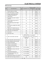
shown in the fault summary table:
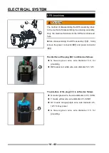
Three-in-one sensor fault inspection
:
◆
Check that the connector is well connected
◆
Check whether the wiring harness and injector pins
are bent or deformed
◆
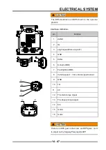
Measure the resistance between M pin and pin G
◆
Measure the voltage of M pin and ECU pin
◆
Measure the resistance of T pin and pin G
◆
Measure the resistance of P pin and pin G
Idle motor fault check:
◆
Check that the connector is well connected
◆
Check whether the wiring harness and injector pins
are bent or deformed
◆
Measure the resistance or voltage between each
stepping motor drive circuit connected to the ECU
and the ground
A
B
C
D
Summary of Contents for SNARLER ATV 2021 Series
Page 1: ...SERVICE MANUAL ATV SERIES PRODUCTS 20210804 V01...
Page 39: ...ENGINE LUBRICATION SYSTEM ENGINE LUBRICATION SYSTEM 3 1 2 Exploded view...
Page 99: ...ENGINE COOLING SYSTEM ENGINE COOLING SYSTEM 3 4 2 Exploded view...
Page 120: ...ENGINE TOP END ENGINE TOP END 3 5 10 Spark Plug Valve Cover Throttle Body Camshaft...
Page 153: ...CVT SYSTEM CVT SYSTEM 3 6 2 L L G G G G R R Lh Lh R R R R Exploded view...
Page 155: ...CVT SYSTEM CVT SYSTEM 3 6 4 R R R R G G R R L L Lh Lh M M G G G G G G...
Page 185: ...4 13 FRONT AND REAR DIFFERENTIAL FRONT AND REAR DIFFERENTIAL...
Page 212: ...COOLING SYSTEM 6 6 Special tools and sealants Silicone Sealant...
Page 230: ...FRONT REAR SUSPENSION 9 2 Exploded view of Front suspension...
Page 232: ...FRONT REAR SUSPENSION 9 4 Exploded view of Rear suspension...
Page 249: ...WHEELS AND TIRES 10 5 Special Tools Jack...
Page 264: ...BRAKE SYSTEM 11 5 Inside Circlip Pliers Special tool...
Page 276: ...STEERING SYSTEM 12 2 Exploded View of Steering System 1 2 A A 3 4 5 5 5 6 3 B...
Page 323: ...ELECTRICAL SYSTEM 14 15 EFI system Schematic diagram of EFI system...
Page 383: ...ELECTRICAL SYSTEM 14 75 B10 B11 B12 B14 B15 B16...


