CRANKSHAFT / TRANSMISSION
CRANKSHAFT / TRANSMISSION
3-2-4
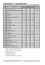
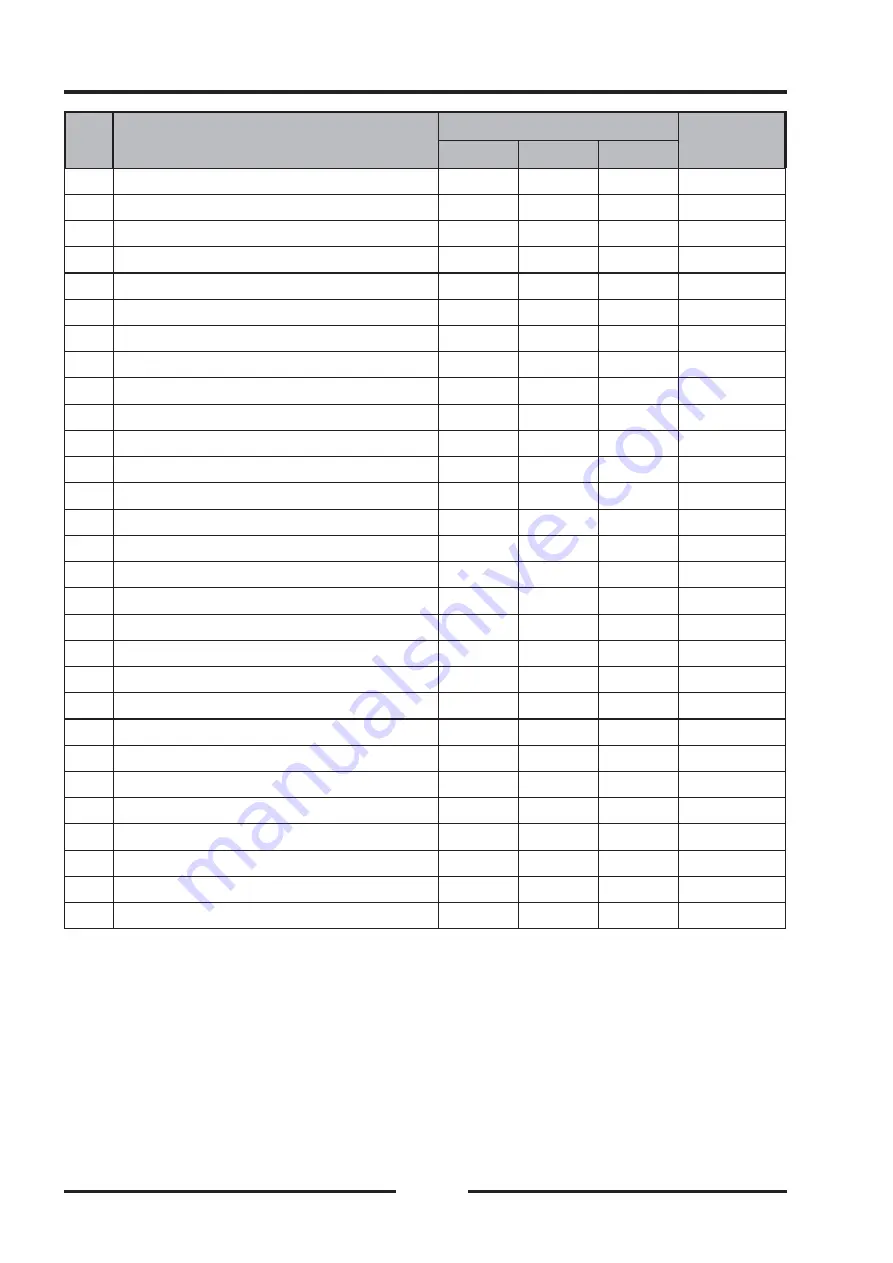
No.
Fastener
Torque
Remarks
N·m
kgf·m
ft·lb
1
Left Crankcase Assembly
SS,O
2
Right Crankcase & Right Cover Combination
SS,O
3
Isolator
4
Bolt M6×65
9.8
1.0
87 in•lb
S
5
Dowel Pin 6×10
6
Bolt M8×40
26
2.7
20
S
7
Needle Roller Bearing HK121612
8
Bolt M8×70
26
2.7
20
S
9
Flow Orifi ce Φ1
2.5
0.25
21 in•lb
L
10
Bearing 6004
O
11
Bearing 6204Z
O
12
Bearing 6206
O
13
Piston Injection Hole Plug
4
0.4
35 in•lb
L
14
Bearing 6304
O
15
Bearing 6203
O
16
Bearing 6006
O
17
Plate,Bearing Retainer
18
Bolt M6×16
9.8
1.0
87 in•lb
L
19
Oil Seal 42×55×8
G
20
Bolt M6×40
9.8
1.0
87 in•lb
S
21
Centrifugal Oil-Air Separator
22
Respirator Cover
23
Circlip 20
24
Oil Seal 20×30×7
G
25
Right Crankcase Cover Gasket
26
Oil Seal 35×52×7
G
27
Bolt M6×30
9.8
1.0
87 in•lb
S
28
Balance Shaft Assembly
29
Crankshaft Connecting Rod Parts
O
G: Apply grease for oil seal and O-ring.
L: Apply a non-permanent locking agent.
O: Apply engine oil.
SS: Apply silicone sealant.
R: Replacement Parts.
S:Follow the specifi c tightening sequence.
Summary of Contents for SNARLER ATV 2021 Series
Page 1: ...SERVICE MANUAL ATV SERIES PRODUCTS 20210804 V01...
Page 39: ...ENGINE LUBRICATION SYSTEM ENGINE LUBRICATION SYSTEM 3 1 2 Exploded view...
Page 99: ...ENGINE COOLING SYSTEM ENGINE COOLING SYSTEM 3 4 2 Exploded view...
Page 120: ...ENGINE TOP END ENGINE TOP END 3 5 10 Spark Plug Valve Cover Throttle Body Camshaft...
Page 153: ...CVT SYSTEM CVT SYSTEM 3 6 2 L L G G G G R R Lh Lh R R R R Exploded view...
Page 155: ...CVT SYSTEM CVT SYSTEM 3 6 4 R R R R G G R R L L Lh Lh M M G G G G G G...
Page 185: ...4 13 FRONT AND REAR DIFFERENTIAL FRONT AND REAR DIFFERENTIAL...
Page 212: ...COOLING SYSTEM 6 6 Special tools and sealants Silicone Sealant...
Page 230: ...FRONT REAR SUSPENSION 9 2 Exploded view of Front suspension...
Page 232: ...FRONT REAR SUSPENSION 9 4 Exploded view of Rear suspension...
Page 249: ...WHEELS AND TIRES 10 5 Special Tools Jack...
Page 264: ...BRAKE SYSTEM 11 5 Inside Circlip Pliers Special tool...
Page 276: ...STEERING SYSTEM 12 2 Exploded View of Steering System 1 2 A A 3 4 5 5 5 6 3 B...
Page 323: ...ELECTRICAL SYSTEM 14 15 EFI system Schematic diagram of EFI system...
Page 383: ...ELECTRICAL SYSTEM 14 75 B10 B11 B12 B14 B15 B16...

