CRANKSHAFT / TRANSMISSION
CRANKSHAFT / TRANSMISSION
3-2-25
CAUTION
CAUTION
The Crankshaft and Connecting Rod are Assembled at
the factory , so the Crankshaft must be replaced as a set.
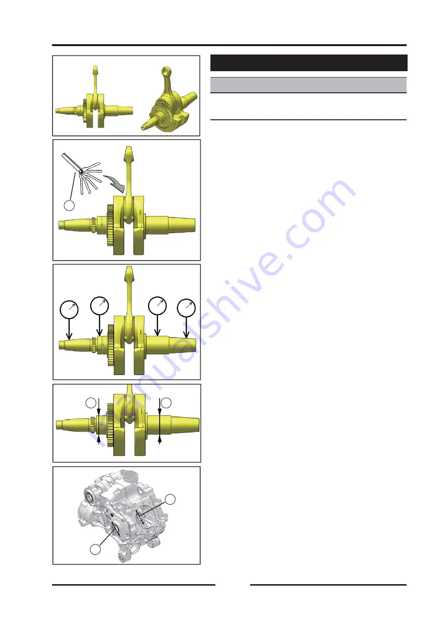
Connecting Rod Big End Side Clearance
Connecting Rod Big End Side Clearance
◆
Measure the side clearance of the connecting rod
big end.
◆
Insert a thickness gauge
【
B
】
between the big end
and either crank determine clearance.
Connecting Rod Big End Side Clearance
Standard: 0.13 ~ 0.48 mm
Service Limit: 0.7 mm
If the clearance exceeds the service limit, replace the
Crankshaft.
Crankshaft Runout
Crankshaft Runout
◆
Measure the crankshaft runout.
If the measurement exceeds the service limit, replace the
Crankshaft.
Standard: TIR 0.04 mm (0.0016 in.) or less
Service Limit: TIR 0.10 mm (0.0039 in.)
Crankshaft Main Bearing/Journal Wear
Crankshaft Main Bearing/Journal Wear
◆
Measure the diameter
【
A
】
of the crankshaft main
journal.
Crankshaft Main Journal Diameter
Standard:
40.995
~ 41.005 mm
Service Limit:
40.97
mm
If any journal has worn past the service limit, replace the
crankshaft with a new one.
◆
Measure the main bearing bore diameter
【
B
】
in the
crankcase halves.
Crankcase Main Bearing Bore Diameter
Standard:
41.040
~ 41.050 mm
Service Limit: 41.08 mm
If there is any signs of seizure, damage, or excessive
wear, replace the crankcase halves as a set.
Crankshaft
A
A
A
A
B
B
B
B
B
B
Summary of Contents for SNARLER ATV 2021 Series
Page 1: ...SERVICE MANUAL ATV SERIES PRODUCTS 20210804 V01...
Page 39: ...ENGINE LUBRICATION SYSTEM ENGINE LUBRICATION SYSTEM 3 1 2 Exploded view...
Page 99: ...ENGINE COOLING SYSTEM ENGINE COOLING SYSTEM 3 4 2 Exploded view...
Page 120: ...ENGINE TOP END ENGINE TOP END 3 5 10 Spark Plug Valve Cover Throttle Body Camshaft...
Page 153: ...CVT SYSTEM CVT SYSTEM 3 6 2 L L G G G G R R Lh Lh R R R R Exploded view...
Page 155: ...CVT SYSTEM CVT SYSTEM 3 6 4 R R R R G G R R L L Lh Lh M M G G G G G G...
Page 185: ...4 13 FRONT AND REAR DIFFERENTIAL FRONT AND REAR DIFFERENTIAL...
Page 212: ...COOLING SYSTEM 6 6 Special tools and sealants Silicone Sealant...
Page 230: ...FRONT REAR SUSPENSION 9 2 Exploded view of Front suspension...
Page 232: ...FRONT REAR SUSPENSION 9 4 Exploded view of Rear suspension...
Page 249: ...WHEELS AND TIRES 10 5 Special Tools Jack...
Page 264: ...BRAKE SYSTEM 11 5 Inside Circlip Pliers Special tool...
Page 276: ...STEERING SYSTEM 12 2 Exploded View of Steering System 1 2 A A 3 4 5 5 5 6 3 B...
Page 323: ...ELECTRICAL SYSTEM 14 15 EFI system Schematic diagram of EFI system...
Page 383: ...ELECTRICAL SYSTEM 14 75 B10 B11 B12 B14 B15 B16...


