ENGINE-ELECTRICAL SYSTEM
ENGINE-ELECTRICAL SYSTEM
3-3-10
Alternator Inspection
Alternator Inspection
There are three types of alternator failures: short, open,
or loss in rotor magnetism. A short or open in one of the
coil wires will result in either a low output, or no output
at all. A loss in rotor magnetism, which may be caused
by dropping or hitting the alternator, by leaving it near an
electromagnetic field, or just by aging, will result in low
output.
◆
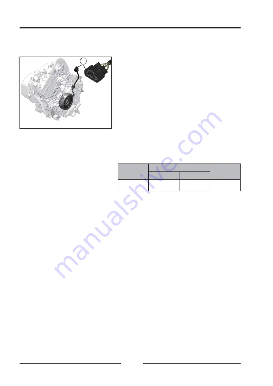
To check the alternator output voltage, perform the
following procedures.
◆
Disconnect the alternator connector
【
A
】
.
◆
Connect a hand tester as shown in the table.
◆
Start the engine.
◆
Run it at the rpm given in the table.
◆
Note the voltage readings (total 3 measurements).
Alternator Output Voltage
Alternator Output Voltage
Tester
Range
Connections
Reading
@3000rpm
Tester (+) to Tester (–) to
250V AC
One yellow
lead
Another
yellow lead
36~54 V
If the output voltage is within the values in the table, the
alternator is operating correctly, and the regulator/rectifi er
is damaged. A much lower reading indicates that
the alternator is defective.
◆
Check the stator coil resistance as follows:
◆
Stop the engine.
◆
Disconnect the alternator connector.
◆
Connect a hand tester as shown in the table.
◆
Note the readings (total 3 measurement).
A
A
Summary of Contents for SNARLER ATV 2021 Series
Page 1: ...SERVICE MANUAL ATV SERIES PRODUCTS 20210804 V01...
Page 39: ...ENGINE LUBRICATION SYSTEM ENGINE LUBRICATION SYSTEM 3 1 2 Exploded view...
Page 99: ...ENGINE COOLING SYSTEM ENGINE COOLING SYSTEM 3 4 2 Exploded view...
Page 120: ...ENGINE TOP END ENGINE TOP END 3 5 10 Spark Plug Valve Cover Throttle Body Camshaft...
Page 153: ...CVT SYSTEM CVT SYSTEM 3 6 2 L L G G G G R R Lh Lh R R R R Exploded view...
Page 155: ...CVT SYSTEM CVT SYSTEM 3 6 4 R R R R G G R R L L Lh Lh M M G G G G G G...
Page 185: ...4 13 FRONT AND REAR DIFFERENTIAL FRONT AND REAR DIFFERENTIAL...
Page 212: ...COOLING SYSTEM 6 6 Special tools and sealants Silicone Sealant...
Page 230: ...FRONT REAR SUSPENSION 9 2 Exploded view of Front suspension...
Page 232: ...FRONT REAR SUSPENSION 9 4 Exploded view of Rear suspension...
Page 249: ...WHEELS AND TIRES 10 5 Special Tools Jack...
Page 264: ...BRAKE SYSTEM 11 5 Inside Circlip Pliers Special tool...
Page 276: ...STEERING SYSTEM 12 2 Exploded View of Steering System 1 2 A A 3 4 5 5 5 6 3 B...
Page 323: ...ELECTRICAL SYSTEM 14 15 EFI system Schematic diagram of EFI system...
Page 383: ...ELECTRICAL SYSTEM 14 75 B10 B11 B12 B14 B15 B16...


