background image

Summary of Contents for PILOT H4

Page 1: ......

Page 2: ......

Page 3: ...PILOT H4 OPERATOR MANUAL ...

Page 4: ...y and is subject to change without notice Seica S p A assumes no liability in case of error or consequential damages that may result from the use or misinterpretation of any of the procedures provided in this publication Seica S p A reserves the right to change the technical specifications without notice Where ever Seica is noted in the present manual it also implies Seica Inc Seica Sarl Seica Chi...

Page 5: ...2 3 2 1 2 ATE rack 2 4 2 1 3 Axis drivers and filters 2 4 2 1 4 Control panel and emergency button 2 4 2 1 5 Cover 2 7 2 1 6 Power supplies 2 7 2 1 7 Motors 2 7 2 1 8 Light indicator or semaphore 2 7 2 1 9 PC main 2 7 2 1 10 Test area 2 8 2 1 11 Measuring heads 2 8 2 2 FIXTURE CONTROL PANEL 2 8 3 GETTING STARTED 3 1 3 1 SYSTEM STARTING 3 2 3 2 TRANSLATION 3 3 3 2 1 Translation 3 3 3 3 TEST PROGRAM...

Page 6: ... 2 PILOT H4 System synoptics 2 2 Fig 3 1 PILOT H4 Run Page of the VIVA software 3 6 Fig 3 2 PILOT H4 Program Report dialog window 3 8 Fig 4 1 PILOT H4 SCAFP Module layout 4 6 Fig 4 2 PILOT H4 F32 P32 Module layout 4 7 Fig 4 3 PILOT H4 S64 Module layout 4 8 Fig 4 3 PILOT H4 OVP board 4 9 Fig 4 5 PILOT H4 System Maintenance dialog window tab Calibration 4 13 Fig 4 6 PILOT H4 System Configuration dia...

Page 7: ...ttle maintenance and offers a high level of system uptime for critical time to market situations The brushless motors used for the horizontal movements of the heads also require little maintenance and the integrated encoders keep the position of the heads constantly under control so no realignment or calibration is necessary after a stop This manual contains all of the required information to use ...

Page 8: ...em that could result from the action described in the warning NOTE Indicates a note a recommendation or a point on which readers should focus more carefully The syntax to select a software menu or menu item is as follows MENU item 1 Select the menu indicated then choose item 1 Example BOARD Select MENU 1 MENU 2 MENU n item 1 Select menu 1 submenu 2 submenu n and then item 1 Example TOOLS HARDWARE ...

Page 9: ...configuration dialog window he Graphical User Interface of the VIVA software provides a set of commands and buttons arranged in horizontal and vertical toolbars Fig 1 2 is an example of the VIVA software GUI Fig 1 2 PILOT H4 Example of VIVA Software GUI Text box A B C Name of the dialog window Tab Radio button Section Checkbox Button ...

Page 10: ...please be sure to have the following info System type System serial number Software release Phone 0039 125 636811 Fax 0039 125 636899 E mail service seica com Mail SEICA S p A Via Kennedy 24 10019 Strambino TO ITALY World Wide Web www seica com 1 5 COMMENTS ABOUT THE DOCUMENTATION You can email to seica seica com if you have comments or suggestions about the documentation 1 6 INTERNET WEBSITE You ...

Page 11: ...s that must be followed P4 Protection panels Protect the system from environmental hazards and prevent users from coming into contact with internal components that can be powered during operation These panels can only be removed with the help of a socket wrench P5 Protective cover It prevents the operator from putting his her arms inside the working area where there can be mechanical parts in moti...

Page 12: ...PILOT H4 Operator Manual 1 6 1 7 3 Safety devices location Fig 1 3 PILOT H4 Safety device location ...

Page 13: ...d WARNING Operation of the PILOTH4 system is very easy however these simple rules should be followed Equipments in motion can be dangerous Despite the safety devices are installed to prevent or reduce to a minimum the operator errors do not perform any actions if not in compliance with the instructions provided WARNING Do not mount any tool on the flying probes that is different from the needle us...

Page 14: ...ys respects what is listed in the Warnings and rules of behavior paragraph and follow the instructions here below The working staff must wear suitable clothing do not wear baggy clothes loose sleeves that can be entangled inside the system during operation Do not wear dangling ties or scarves necklaces bracelets and rings Long hair wear a cap if necessary Moreover if the operator rashly inserts hi...

Page 15: ...P44 230VAC 120 Vac TYPE SO 3Xawg12 CONDUCTORS NEOPRENE JACKET UNSHIELDED 90 C 600 Volt Cable length not more than 5 meters Socket outlet 230 Vac Series 62 IEC 309 2P 50 60Hz 15 IP44 230VAC 120 Vac NEMA L5 30R for 110VAC 50 60 Hz 15 The power supply source must be located not more than 5 meters approx 15 feet from the PILOTH4 and must be accessible by an operator The power supply source must be pro...

Page 16: ...ied with a dew point of 10 Celsius Compressed air supply Typical 4 Atm Max 6 Atm Air supply setting Min 4 5 Atm Typ 5 5 Atm Max 6 Atm Air flow Min 1N l Air compressor capacity Min 10 l min Air input 3 8 Female with GAS thread Air hose to system 3 8 ID Minimum 1 8 4 Weight System weight 1577 Kg 3469 lb System weight with packing 1800 Kg 3960 lb ...

Page 17: ...round the system to ensure good air circulation for the electronics and to have enough space for easy access to the inspection and maintenance points The following is a scale drawing of the required work area and the place usually occupied by the operator Fig 1 4 PILOT H4 System layout Fig 1 5 PILOT H4 Side view and front view ...

Page 18: ... in order to guarantee a good air circulation for the electronics onboard and to have sufficient space to access the inspection maintenance points of the system The figures 1 4 and 1 5 respectively show the system layout and the work area with overall dimensions Fig 1 6 PILOT H4 Work area Height 1480mm 58 27 Length 1740mm 68 50 Width 1330mm 52 36 ...

Page 19: ... overview B1 Front doors for easy access to all the systems electronic racks and components B2 Side panel B3 Protective cover tiltable protecting the work area B4 PC compartment door B5 Tiltable keyboard mouse support B6 Control Panel B7 Work area B8 LCD Monitor ...

Page 20: ...ctional blocks interacting together The picture below illustrates the system general architecture What follows is a technical description for every block Fig 2 2 PILOT H4 System synoptics 1 Light indicator 2 SMEMA connection 3 Air filter and tap 4 Main ON OFF Switch 5 System power plug 4 1 2 3 5 CONS22 ...

Page 21: ...ce sockets available to the user F1 46Vac 3A Board Handler motion drives protection Not present F2 19Vac 3A Board Handler sensors protection Not present F3 220Vac Protection of all units supplied with 230Vac F4 24 Vac 3A Contactors power supply circuits protection F5 Not present F6 Not present F7 Not present F8 230Vac 20A X axes power supply AC input protection F9 95 Vac 20A Y axes power supply AC...

Page 22: ...em there are the axis drivers and filters They control the head movements along the X Y and Z axis generating the proper signals to drive the axis motors 2 1 4 Control panel and emergency button It is composed of LEDs and buttons that informs the operator of the status of the system system stopped system working system in error The control panel is located on the left side of the system above the ...

Page 23: ...owers motor axes OFF MOTOR ON OFF MOTOR OFF OFF LED DESCRIPTION LIGHT ATE ON All test system instruments are powered ATE ON ON ATE OFF OFF ATE OFF All test system instruments are depowered ATE ON OFF ATE OFF OFF The pedal is factory configured to behave in the same way as the fixture control panel buttons for operator s comfort It can open close the clamps like the UPPER LOWER button or block unbl...

Page 24: ...MERGENCY It immediately stops the system it stops any movements of axes and probes switching OFF the power The Personal Computer remains ON BUTTON DESCRIPTION START It starts the test BUTTON DESCRIPTION STOP It stops the TEST It resets the condition insufficient air caused by a inadvertently fall of pressure ...

Page 25: ...he system operating conditions as illustrated below DESCRIPTION GREEN ORANGE RED System in AUTO mode waiting for a board for more than 40 seconds System in AUTO mode ready for a board System in AUTO or MANUAL mode The cycle is not active waiting for operator Probes in movement or there is board on board clamping System Failure in MAN or AUTO mode Green color ON Intermittent 0 5 seconds ON 0 5 seco...

Page 26: ...ation directions of the 3 axes are X axis Horizontal translation from right to left and vice versa Y axis Horizontal translation from front to rear and vice versa Z axis Vertical translation from top to bottom and vice versa 2 2 FIXTURE CONTROL PANEL The fixture control panel is located into the work area and helps the operator to block the PCB rails in particular for the flexible ones The three b...

Page 27: ...s a good rule to check some parameters and setting in order to obtain the desired result In this chapter there are all operations necessary to start the test activity together with the description of all parameters present in the different dialogs that appear on the screen ...

Page 28: ...WITCH on the rear side of the system to 1 Press the button MAIN ON on the control panel the light indicator of the button will turn ON Press the button MOTOR ON on the control panel the light indicator of the button will turn ON Press the button ATE ON on the control panel the light indicator of the button will turn ON ...

Page 29: ...esting because if it is not carried out accurately the probe will not be positioned correctly on the supports and could yield to a higher percentage of false errors To attain a correct translation make sure that appropriate measures are taken It is advisable to select the points visually holding the board sample in order to verify that the points selected are appropriate for testing purposes It is...

Page 30: ...is The camera will be positioned on the co ordinate of the first point selected for the translation displayed in window Set Reference points The co ordinate reached by the camera may not correspond to the correct position on the board In this case it is necessary to align the two points The following step explains how to perform this operation 3 Position the cross displayed on the center of the se...

Page 31: ...5 Align TP2 in the same way as for TP1 6 Press the icon again The system checks that the coordinates acquired with the camera correspond to the theoretical points previously selected in the Definition of Reference Points If there is an error on the two point distance the system will give a fail report and suggest to cancel the operation or to acquire the two values again 7 If no error is visualize...

Page 32: ...follow the instructions in the section System Starting 3 3 1 TEST ENVIRONMENT 1 If not already opened press the button to enter the Wizard Environment The following dialog windows is displayed Fig 3 1 PILOT H4 Run Page of the VIVA software Once you are in the Run page press the button to start the test program To stop the test program execution before it has been completed it is possible to Press ...

Page 33: ...the tests with fail result upon completing the test program execution If the checkbox Automatic Error Retest after Test in the Board Configuration Environment is selected the button is selected You may change its status from the Debug Environment Stop and retest on Error In case of error the program is stopped and the system prompts a dialog to display the information related to the measurements p...

Page 34: ... report Press the button to print the test report Press the button to have a print preview of the test report Press the button to set the error message format Small 100 R1 error percentage Component Name Medium 100 R1 Device error percentage Component Name component denomination Large 100 R1 Device Values error percentage Component Name component denomination measured value and measure range Press...

Page 35: ...ton will turn OFF 2 Press the button on the control panel the light indicator of the button will turn OFF 3 Press the button on the control panel the light indicator of the button will turn OFF 4 Set the MAIN SWITCH on the rear side of the system to 0 5 Close the air tap located on the rear side of the system ...

Page 36: ...e fixed probe is held in place by a magnet located on the probe base that fixes it to the bottom of test area 3 6 1 Fixed probe positioning 1 Place the board in the work area 2 On the board acquire the point that will be used for fixed probe and assign a name 3 Repeat camera movement and point acquisition as many times as the number of fixed probes to add 4 Remove the board from the work area 5 Mo...

Page 37: ... board from bending during test especially when the board is not rigid enough They are similar to a fixed probe but they do not have a needle or a connection cable For support positioning refer to similar instruction above used to position the fixed probe ...

Page 38: ......

Page 39: ...eck of the air filter Daily Replacement of the air filter When the filter becomes dark colored System diagnostics Weekly or when a problem is suspected Replacement of probe needle Approximately after a million hits Probe calibration After each maintenance operations on Z axes Openfix calibration After each maintenance operations on Openfix probe replacement Board handler calibration When automatic...

Page 40: ...pection frequency is related to the quality of the centralized air compressor system A daily check is suggested in any case 4 2 1 Replacing the filter The air filter is located on the back of the system Here are listed the operations to follow to replace the filter part number PM FILTC0ND 00 1 Move the air tap to OFF position to close air 2 Push the black button on the filter pot downwards and at ...

Page 41: ... carried out interactively to allow users to select which ATE modules have to be tested At the end of the interactive test users can save the diagnostic configuration set so that it can be called at a later stage Option CUSTOM this option enables to call a diagnostic configuration stored during an interactive diagnostic procedure The selection of button opens a dialogue that facilitates the select...

Page 42: ...to check the motion of the four mobile probes along axes X and Y Options section Number of Iteration this field specifies how many times the diagnostic test has to be performed Print Errors if checked this field enables the user to print the results of the diagnostic program 4 3 2 Meaning of the error messages At the end of the diagnostic test the system displays the results of the individual test...

Page 43: ...ica s Customer Service FIXED OPENS PROBES Any Contact Seica s Customer Service Tab 4 2 Table of corrective actions 1 n indicates the channel number of the system p indicates the channel number of the board s indicates the board number 2 The number of channels is always counted on 64 basis The way of interpreting the result varies according to the type of channel modules mounted on the system The e...

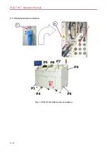
Page 44: ...PILOT H4 Operator Manual 4 6 SCAFP board layout Fig 4 1 PILOT H4 SCAFP Module layout ...

Page 45: ...maintenance operations 4 7 F32 P32 board layout Fig 4 2 PILOT H4 F32 P32 Module layout ...

Page 46: ...OT H4 Operator Manual 4 8 S64 board layout Fig 4 3 PILOT H4 S64 Module layout LI1 LI1 LI2 LI2 LI3 LI3 LI4 LI4 LI1 LI2 LI3 LI4 LI1 LI2 LI3 LI4 LI1 LI2 LI3 LI4 LI1 LI2 LI3 LI4 LI1 LI2 LI3 LI4 LI1 LI2 LI3 LI4 ...

Page 47: ...test area with the TOP side facing upwards Select the OVP program as if it were an ordinary test program Before performing a test with OVP program it is advisable to carry out an automatic translation using channels 124 TP61 1 and 61 TP108 1 If the result of the test is FAIL contact the your nearest Seica support office for further information Fig 4 4 PILOT H4 OVP board ...

Page 48: ... needle support 4 5 Remove the needle 5 and take it out from the top install a new needle 6 Mount the white needle support 4 and insert the internal socket head screw using a 2mm Allen wrench 3 7 Move the cable guide upwards and tighten the screws 2 8 Hold cable 1 with hands and connect it to the probe support 9 Press and The light indicator of each button will turn ON 10 Perform the homing proced...

Page 49: ...ews without tightening them 9 Push the Openfix probe upwards until it stops and only then tighten the related screws 10 Insert the cable into its arranged path move the cable guide upwards 3 until it stops and then tighten the screws 11 Stretch the cable and fix it into the cable guide 6 12 Give the cable the same shape it had before the replacement Connect the connector into its position 4 13 Fix...

Page 50: ... its original position c every time the system is moved from its original position d if the system has not been used for a long time e Every time any of the probes appears to be out of its position during the test f All the calibrations are carried out using the OVP check board hence this board should be loaded into the system before starting the calibration procedures Run VIVA software In the pag...

Page 51: ...maintenance operations 4 13 Fig 4 5 PILOT H4 System Maintenance dialog window tab Calibration ...

Page 52: ... select all the options to calibrate the electrical probes and launch the calibration of the following items installed on the heads Electrical Probes Mobile Capacitive Probe Power Probes Stampers Note It is always recommended to perform the Electric Probe calibration first regardless of the type of calibration needed Please refer to the instructions reported in the dedicated chapters below ...

Page 53: ...calibration It is performed by Seica before delivering the system 4 6 3 ELECTRICAL PROBES CALIBRATION This procedure allows to automatically calibrate the measuring probes as compared to XY Z axes 1 Insert the OVP board into the work area positioning it as shown in Fig 4 7 Fig 4 7 PILOT H4 OVP Board 2 Close the protective doors 3 Select the checkboxes as indicated in Fig 4 5 Probes Z Alignment X a...

Page 54: ... Configuration dialog select items Probes Z Alignment and X and Y Alignment See fig 3 10 Fig 4 8 PILOT H4 Setting the Electrical Probe Calibration Set the value of field Check Board Set Area Number to 2 Select Probe type as shown in the picture ...

Page 55: ... operations 4 17 Press the button for each electrical probe installed Here 1 and 3 and press Follow the instructions on screen and press YES to continue Follow the instructions on screen and press YES to continue ...

Page 56: ...next picture to continue Press if the probe is not in that area and go on the next picture Use the joystick to move the Probe 1 over the central round probing area of the check board and press to continue When the electrical probe calibration has been completed a dialog will be displayed to perform the X alignment of the Top camera see fig 3 11 ...

Page 57: ...maintenance operations 4 19 Press the button for higher accuracy Fig 4 9 PILOT H4 Set Camera X TOP dialog window Now adjust the X alignment of the Top camera with the arrow keys Press to continue ...

Page 58: ... dialog will be displayed to perform the Y alignment of the Top camera Press the button for higher accuracy Fig 4 10 PILOT H4 Set Camera Y TOP dialog window Now adjust the Y alignment of the Top camera with the arrow keys Press to continue ...

Page 59: ...tions 4 21 Align the Top Camera and the Bottom camera on the same hole on the Check Board Use the arrow keys to center the view finder on the hole for the Top camera Fig 4 11 PILOT H4 Align top camera Press to continue ...

Page 60: ...PACITIVE PROBE CALIBRATION In the dialog System Configuration select the checkbox Mobile Opens Probe CPM then press Fig 4 12 PILOT H4 Setting the Mobile Opens Probe Calibration Follow the instructions on screen and press YES to continue when done ...

Page 61: ...ons 4 23 Follow the instructions and press YES to continue when done In the dialog Calibration Mobile Open Probe press the button to zoom in for more accuracy Fig 4 13 PILOT H4 Calibration Mobile Open Probe dialog window ...

Page 62: ...he arrow keys to adjust the alignment of the red circle over the top of the capacitive probe Press to save the new X Y position Repeat the same steps to align the bottom side of the capacitive probe and press to save the new X Y position ...

Page 63: ...maintenance operations 4 25 4 6 5 STAMPER CALIBRATION In the System Configuration dialog select the checkbox Stamper See fig 3 19 and press Fig 4 14 PILOT H4 Setting the Stamper Calibration ...

Page 64: ...al 4 26 Follow the instructions and press YES to continue Follow the instructions and press YES to continue In the dialog displayed press the button to zoom out and enlarge the view to search the mark if it is not displayed ...

Page 65: ...maintenance operations 4 27 Center the mark with the red circle using the joystick or the arrow keys Press to save the new calibration ...

Page 66: ...a little grease by hand spreading it uniformly on the ball screws The ball screws layout is shown in the figure below 4 8 LUBRICATING THE PROBE GUIDE X DIRECTION We recommend lubricating X probe guide with a small quantity of grease for high speed movements every 1000 hours Apply a little grease by hand spreading it uniformly on the guide The Y probes guides don t need any lubrication ...

Page 67: ...ned and manufactured in accordance with the main safety European requirements Each system has got an identification label with a logo that certifies the compliance with these directives The figure below shows an example of the abovementioned label PILOT H4 ...

Page 68: ...EM Seica S p A declines any liability for data loss caused by the fault to comply with the instructions included in this section It is always recommended to make a backup copy of the Recovery DVD and store it in a safe place 5 2 PC SETTINGS Before performing the system recovery configure your PC to bootstrap from CD DVD Refer to the instructions provided in the PC User Guide included in the docume...

Page 69: ......

Page 70: ......

Reviews: