


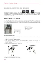


maintenance operations
4-5
MODULE
ERROR
SOLUTION
ACLAM
Any
Contact Seica's Customer Service
CHANNEL BOARD
S64
% SH LN 1 CH n (p/s)
(1)
Replace the faulty relay on line 1.
% SH LN 2/3 CH n (p/s)
(1)
Replace the faulty relay on lines 2 and/or 3.
% SH LN 4 CH n (p/s)
(1)
Replace the faulty relay on line 4.
% OP LN 1/2 CH n (p/s)
(1)
Replace the faulty relay on lines 1 and/or 2
% OP LN 3/4 CH n (p/s)
(1)
Replace the faulty relay on lines 3 and/or 4.
CHANNEL BOARD
SCAFP
% SH LN 1 CH n (p/65)
(1)
Replace the faulty relay on line 1.
% SH LN 2/3 CH n (p/65)
(1)
Replace the faulty relay on lines 2 and/or 3.
% SH LN 4 CH n (p/65)
(1)
Replace the faulty relay on line 4.
% OP LN 1/2 CH n (p/65)
(1)
Replace the faulty relay on lines 1 and/or 2
% OP LN 3/4 CH n (p/65)
(1)
Replace the faulty relay on lines 3 and/or 4.
Problems other than those
described above
Contact Seica's Customer Service
CHANNEL BOARD
F32 / P32
% SH LN 1 CH n (p/s)
(1)(2)
Replace the faulty relay on line 1.
% SH LN 2/3 CH n (p/s)
(1)(2)
Replace the faulty relay on lines 2 and/or 3.
% SH LN 4 CH n (p/s)
(1)(2)
Replace the faulty relay on line 4.
% OP LN 1/2 CH n (p/s)
(1)(2)
Replace the faulty relay on lines 1 and/or 2
% OP LN 3/4 CH n (p/s)
(1)(2)
Replace the faulty relay on lines 3 and/or 4.
Problems other than those above Contact Seica's Customer Service
FIXED OPENS
PROBES
Any
Contact Seica's Customer Service
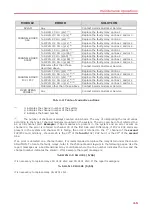
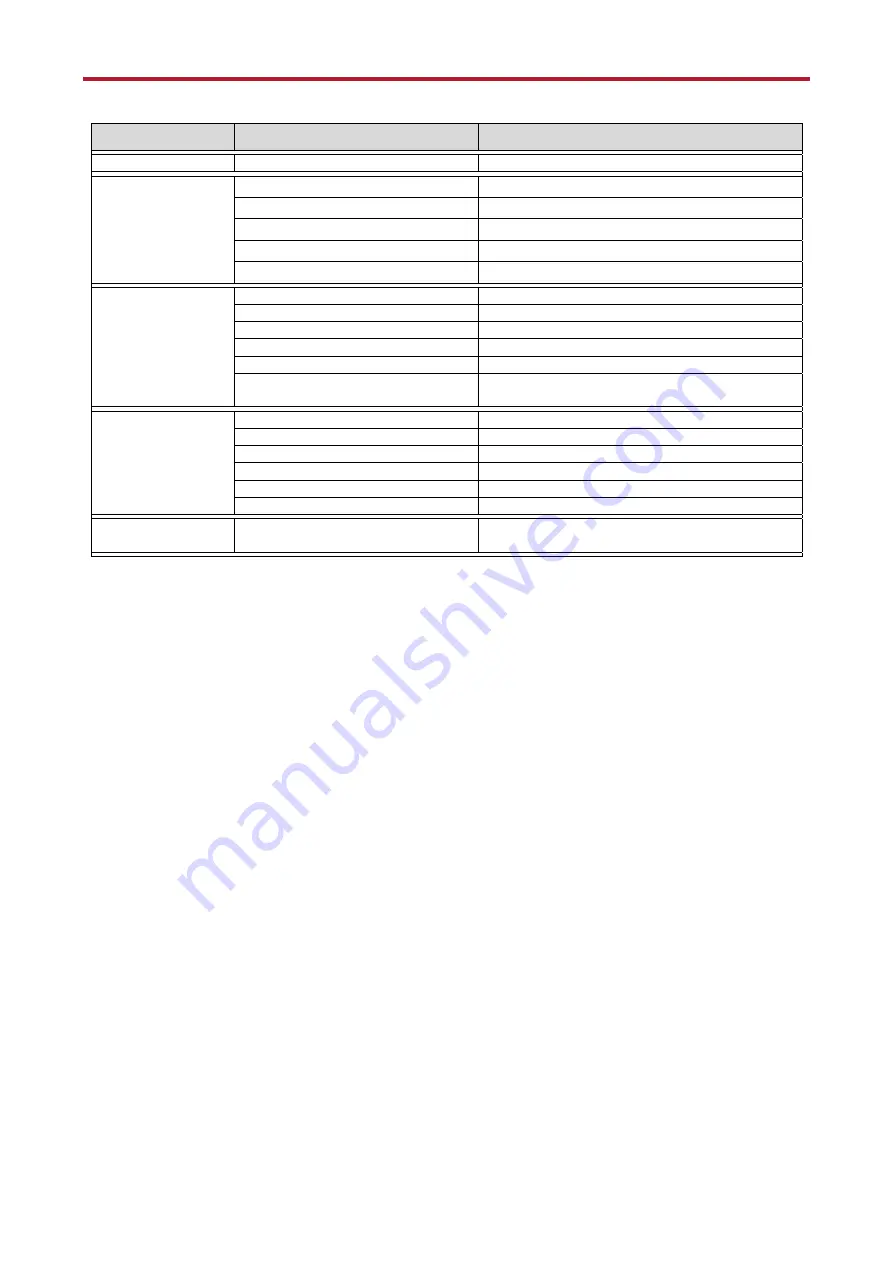
Tab. 4-2: Table of corrective actions
(1)
n: indicates the channel number of the system
p: indicates the channel number of the board
s: indicates the board number
(2)
The number of channels is always counted on 64-basis. The way of interpreting the result varies
according to the type of channel modules mounted on the system. The error can be in fact referred to a
64 or 32-channel card. Example: if S64 modules are present in the system and an error occurs on
channel 33, the error is referred to channel 33 of the first S64 card. Differently, if F32 or P32 cards are
present in the system and channel 33 is failing, the error is referred to the 1
st
channel of the second
F32/P32 card. Similarly, channel 125 is the 29
th
of the fourth F32 / P32 but it is the 29
th
of the second
S64.
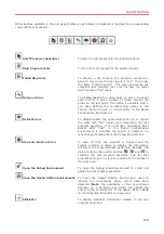
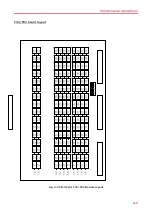
If an error is detected on a channel board, it is recommended to replace the relay listed under the column
SOLUTION. To locate the faulty relays, refer to the channel boards layouts in the following pages. Use the
report messages as a bi-dimensional array coordinate where the line number indicates the row and the
channel number indicates the column. If for example the report message is:
% SH LN 2/3 CH 4101 (5/65)
it is necessary to replace relays CH 4101 LN 2 and CH 4101 LN 3. If the report message is:
% SH LN 1 CH 4101 (5/65)
it is necessary to replace relay CH 4101 LN 1.
Summary of Contents for PILOT H4
Page 1: ......
Page 2: ......
Page 3: ...PILOT H4 OPERATOR MANUAL ...
Page 38: ......
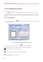
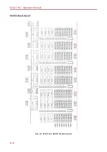
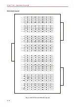
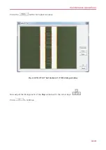
Page 44: ...PILOT H4 Operator Manual 4 6 SCAFP board layout Fig 4 1 PILOT H4 SCAFP Module layout ...
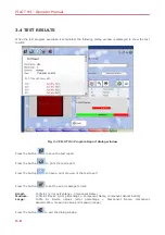
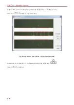
Page 45: ...maintenance operations 4 7 F32 P32 board layout Fig 4 2 PILOT H4 F32 P32 Module layout ...
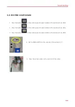
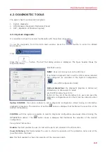
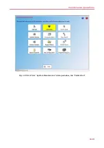
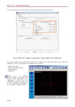
Page 51: ...maintenance operations 4 13 Fig 4 5 PILOT H4 System Maintenance dialog window tab Calibration ...
Page 69: ......
Page 70: ......


