background image

Version Nr. 1-22 - 20.03.2022

Doc. No. 99874000201USL

2 / 19

1. User manual

This instruction manual contains information and instructions to enable the user to work safely, correctly and
economically on the unit. Understanding and adhering to the manual can help one:

Avoid any dangers.

Reduce repair costs and stoppages.

Extend and improve the reliability and working life of the unit.

PLEASE ENSURE TO USE THE RIGHT VERSION OF THE INSTRUCTION MANUAL SUITABLE FOR YOUR
UNIT.

Intended use
The unit is to be used exclusively for the dissipation of heat from control cabinets and enclosures in order to
protect temperature sensitive components in an industrial enviorment. To meet the conditions of use, all the
information and instructions in the instruction manual must be adhered to.

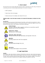
General danger
Indicates compulsory safety regulations which are not covered by a specific
pictogram such as one of the following.
 

High electric voltage
Indicates electric shock danger.

Important safety instruction
Indicates instructions for safe maintenance and operation of the unit.
 

Attention
Indicates possible burns from hot components.
 

Attention
Indicates possible damage to the unit.
 

Instruction
Indicates possible danger to the environment.

2. Legal regulations

Liability
The information, data and instructions contained in this instruction manual are current at the time of going to
press. We reserve the right to make technical changes to the unit in the course of its development. Therefore,
no claims can be accepted for previously delivered units based on the information, diagrams or descriptions
contained in this manual. No liability can be accepted for damage and production caused by:

Summary of Contents for 874000201USL

Page 1: ...tions 3 4 Settings 4 5 Functional principle 5 6 Technical data 6 7 Mounting 7 8 Condensate management 8 9 Mounting Principle 9 10 Electrical connection 10 11 Controller 12 12 Wiring diagram 16 13 Taking into operation 17 14 Trouble shooting 17 15 Maintenance Cleaning 18 16 Transport Storage 19 17 Parts supplied Spare parts Accessories 19 ...

Page 2: ...he instruction manual must be adhered to General danger Indicates compulsory safety regulations which are not covered by a specific pictogram such as one of the following High electric voltage Indicates electric shock danger Important safety instruction Indicates instructions for safe maintenance and operation of the unit Attention Indicates possible burns from hot components Attention Indicates po...

Page 3: ...read with regards to Safety instructions Instructions on taking the cabinet out of operation Instructions on the prevention of unauthorised cabinet reconnection The electric equipment meets the valid safety regulations One can find dangerous voltages above 50 V AC or above 100 V DC Behind the control cabinet doors On the power supply in the unit housing The unit has to be operated according to the ...

Page 4: ...net air does not come into contact with the ambient air which may well be dirty or polluted Enclosure cooling units can dissipate large quantities of heat from sealed enclosures such as electrical enclosures into the ambient air and at the same time reduce the cabinet internal temperature to below that of the ambient air The unit can function without problems in extreme ambient conditions e g dust...

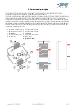
Page 5: ...rant thus taking it to high pressure and high temperature and pushes it through the condenser where it is cooled by ambient air thus passing from the gas to the liquid state At the liquid state it then passes through the capillary pipe being a much lower pressure the refrigerant arrives to the evaporator where it absorbs the necessary heat to change from liquid to gas state The gas is then drawn b...

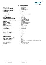
Page 6: ... 880 cfm Enclosure 520 880 cfm Mounting Wall mounted Housing Material Mild steel powder coated Dimension H x W x D 40 9 x 17 9 x 14 6 inch Weight 144 lbs Voltage Frequency 230 V 50 60 Hz UL Voltage Frequency 230 V 60 Hz Current 95F95F 9 5 A 50 Hz 12 4 A 60 Hz Starting current 50 A Max current 14 5 A Nominal power 95F95F 1 85 kW 50 Hz 2 4 kW 60 Hz Max power 3 4 kW Fuse 20 A T Max circuit ampacity 1...

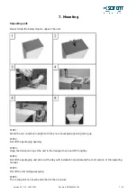
Page 7: ...re cut packaging opening facing up STEP 2 Pull off the packaging opening STEP 3 Hang the transport loop of the unit in the transport hook and lift it slightly STEP 4 Pull off the packaging and slide out the tray with installation material and the short version of the operating manual STEP 5 Pull off the remaining packaging STEP 6 The cooling unit can now be attached to the enclosure ...

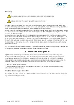
Page 8: ...ed by storage conditions please check this template by verifying values of the largest dimensions before drilling Fit the sealing strip on the cooling unit on the side connected to the enclosure and follow the installation diagram This AC unit can only be mounted to a suitably Type rated enclosure to maintain it s Type rating The Type and IP rating of the enclosure should be the same or higher tha...

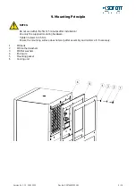
Page 9: ... within the first 15 minutes after installation Use only the supplied mounting hardware Tighten Screws to 4 5 Nm Ensure the mounting surface does not warp after assembly and reinforce it if necessary 1 M6 bolts 2 M6 toothed washers 3 M6 Flat washers 4 Enclosure 5 Mounting gasket 6 Cooling unit ...

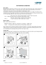
Page 10: ...if closed Door contact terminals bridged or NC door switch connected contact must be closed when cabinet door is closed c68 1 ON if open Remove bridge or NO door switch connected contact must be open when cabinet door is closed Alarm Contacts Alarm contacts rated according to EN60730 1 8 4 A N O 6 4 A N C 2 2 A N O N C 250Vac 100000 cycles UL 873 8A resistive 2FLA 12LRA pilot duty C300 250Vac 3000...

Page 11: ... 03 2022 Doc No 99874000201USL 11 19 Refer to UL508A Supplement SB and Seifert Systems document Short Circuit Current Rating SCCR on methods how to modify the available short circuit current within a circuit in the panel ...

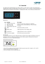
Page 12: ...ogress 2 Alarm relay active 3 Heater relay active 4 Ambient blower relay active Alarm Flashes when alarms are active Heating mode Signals operation of unit in heating mode Cooling mode Signals operation of unit in cooling mode TEST Test mode in progress Activated only by manual procedure Programming The operating parameters can be modified using the front keypad Access differs depending on the type ...

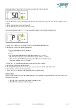
Page 13: ...re C 0 F 1 P25 for low temperature alarm threshold default 10 C 14 F P26 for high temperature alarm threshold default 55 C 131 F c68 for door contact NO NC logic change 0 ON if closed 1 ON if open Controller firmware rev 1 2 or higher 3 Press SET on the desired parameter to display the current value 4 Use or to reach the desired value 5 Pressing SET temporarily saves the new value and returns to th...

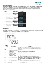
Page 14: ... with an icon flashing triangle alternating with the standard display If more than one error occurs these are shown in sequence on the display Failure Code Description Solution OFF Door open Close the enclosure door and check the door contact switch If no door contact switch is used and c68 0 bridge terminals on power connector Incorrect phase sequence 3 phase units Displayed on power up Check phas...

Page 15: ... button for at least 5 seconds When pressing PRG for 3 seconds the firmware revision code is displayed for 2 seconds When cleaning the controller panel do not use ethanol hydrocarbons ammonia or their by products Use neutral detergents and water In order to protect the unit s components minimum relay output on 3 or 7 minutes and off 4 minutes times and minimum time 7 or 11 minutes between activation...

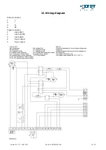
Page 16: ...Version Nr 1 22 20 03 2022 Doc No 99874000201USL 16 19 12 Wiring diagram Power connector 1 L 2 3 N 4 PE Signal connector 1 Alarm NC 2 Alarm COM 3 Alarm NO 4 Door contact 5 Door contact ...

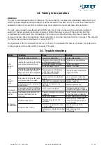
Page 17: ...ressor don t work Enclosure temperature is below setting temperature St Verify values of parameter St Door switch contact is open Verify door switch Controller doesn t work Replace controller Internal fan works external fan and compressor don t work Display shows alternating OFF and temperature The sequence of the phases inside the power supply connector is incorrect Change phases inside power sup...

Page 18: ...ld be replaced immediately Do not use a steam jet or high pressure to clean the filter mats Do not wring out the filter mats If the ambient air is extremely oily we recommend the use of metal filters see accessories They can be cleaned with standard cleaning agents and reused In addition the unit should have regular functional tests approx every 2 000 hours depending on the grade of ambient pollution...

Page 19: ... F max 95 the air conditioner should always be stored according to the installation position Returning the unit To avoid transport damage the unit should be returned in the original packing or in a packing case and must be strapped to a pallet If the unit cannot be returned in the original packing please ensure that A space of at least 30 mm must be maintained at all points between the unit and th...

Reviews: