


6
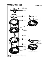
TECHNICAL GUIDE
Cal. A860A, A861A
• Do not disassemble the switch spring (B) and its washer except when they need to be replaced.
• When installing the switch spring (B), take care not to set it in the wrong direction. (See the exploded
view on page 3.)
11
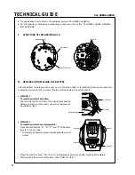
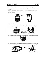
Battery
•
How to install
Set the battery with its (-) side down.
12
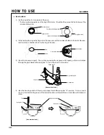
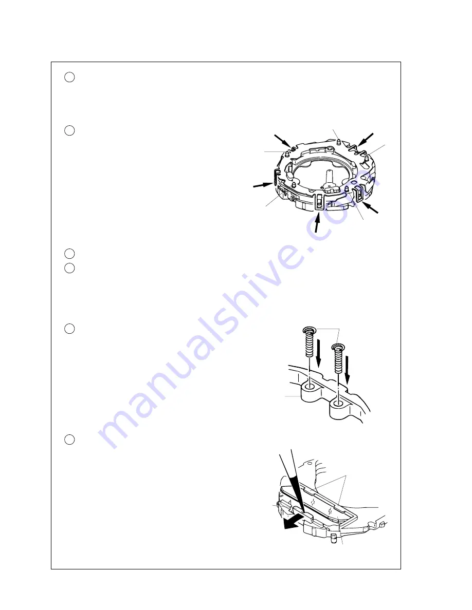
Switch spring (A)
•
How to remove
Release the five hooking portions of the switch spring
(A) indicated by the arrows in the illustration at right,
and then, lift it up to remove.
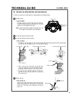
•
How to install
Set the switch spring (A) to the guide posts “a”, “b”,
“c”, “d” and “e” in the illustration at right, and then,
have the five hooking portions of the switch spring
catch the module securely.
a
e
c
b
d
13
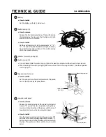
Washer for switch spring (B)
14
Switch spring (B)
•
How to install
Set the end portion of smaller diameter to the guide
hole of the liquid crystal panel frame.
19
Speaker lead terminal
Liquid crystal
panel frame
Speaker lead terminal
20
Liquid crystal panel
•
How to remove
Release the hooking portion of the liquid crystal panel
frame (“A” portion in the illustration at right) by
moving it in the direction of the arrow with the tip of
tweezers, and remove the liquid crystal panel.
•
How to install
Slip the liquid crystal panel into the gap under “B”
portions of the liquid crystal panel frame, release “A”
portion by moving it in the direction of the arrow with
the tip of tweezers, and then, set the liquid crystal
panel.
“B” portion
“A” portion
Liquid crystal panel
Summary of Contents for A860A
Page 11: ......
Page 12: ...99 1 Printed in Japan...


