background image

33 

11. FUNCTION SETTINGS 

This printer can set various functions according to use conditions and intended use.   

The setting contents are stored in the Memory Switch (hereinafter referred to as MS) in the FLASH 

memory mounted in the printer, and it is possible to set MS by using the switches or command input. 

This section describes the setting procedure by using the switches. 

See "22. MS SETTINGS LIST" for the MS setting list. 

NOTE 


Be sure to set the value as instructed when "Fixed" is stated for 0 or 1 in the table.   
Otherwise, the printer may not work correctly or may crash. 


HINT 

  See "MP-A40 SERIES THERMAL PRINTER TECHNICAL REFERENCE" for details of 

the function settings by using the switches and other methods. 

  When neither switch is pressed within 30 seconds after the message is printed, the printer 

exits the Setting Mode and returns to the print-ready status. 


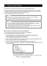
 Procedure for Setting Functions Using Switches 

To set the functions using the switches, set the printer in the Setting Mode. 

To enter the Setting Mode, follow the procedure below. 
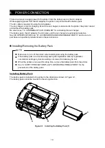
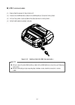
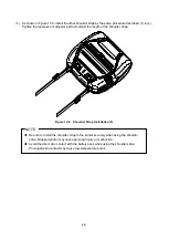
(1) 

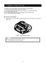
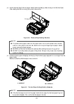
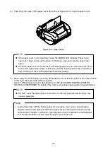
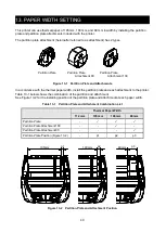
Install the thermal paper in the printer as instructed in "9. THERMAL PAPER SETTING". 

And check that no error occurs, and then turn off the printer.   

See "7. LED DISPLAY OF PRINTER" for the error status. 

(2) 

Press the POWER Switch while holding down the FEED Switch. Release the POWER Switch first.   

When the test print is started, release the FEED Switch. 
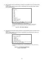
(3) 

After the test print, the mode selection message is printed as shown in Figure 11-1. 

To enter the Setting Mode, select "1 : Setting Mode". (Press the FEED Switch once, and then press 

the POWER Switch.) 


"4 : Print WLAN Information" is printed only for the Wireless LAN model. 


When pressing the FEED Switch once, "1 : Setting Mode" is selected. 


When pressing the POWER Switch without pressing the FEED Switch, "0 : Normal Mode" is selected. 

Figure 11-1    Mode Selection Message 


[Mode Select] 
0 : Normal Mode 
1 : Setting Mode 
2 : Wireless ON/OFF Mode 
3 : Hex Dump Mode 
4 : Print WLAN Information 
Press the FEED switch an equal 
number of times to the selected number. 
After that, press the POWER SW. 

Summary of Contents for MP-A40 SERIES

Page 1: ...USER S GUIDE Thermal Printer MP A40 SERIES Read this USER S GUIDE carefully before using the printer Keep this USER S GUIDE in a place where it can be accessed quickly ...

Page 2: ...countries and is used under license All other trademarks are the properties of their respective companies Applicable EC Directive and Standards Product Thermal Printer MP A40 B Directive Title 2014 53 EU Radio Equipment Directive 2011 65 EU Restriction of the use of certain hazardous substances RoHS Directive Standards EN 301 489 1 EN 301 489 17 EN 300 328 EN 60950 1 EN 50581 Product Thermal Print...

Page 3: ...and if not installed and used in accordance with the instruction manual may cause harmful interference to radio communications Operation of this equipment in a residential area is likely to cause harmful interference in which case the user will be required to correct the interference at his own expense The changes or modifications not expressly approved by the party responsible for compliance coul...

Page 4: ...fications on the printer This USER S GUIDE consists of the following sections 1 INTRODUCTION 1 2 SAFETY PRECAUTIONS 2 3 OPERATING PRECAUTIONS 7 4 PREPARATION 11 5 IDENTIFYING THE MODEL TYPE 13 6 EACH PART OF PRINTER 14 7 LED DISPLAY OF PRINTER 16 8 POWER CONNECTION 19 9 THERMAL PAPER SETTING 23 10 TEST PRINT 27 11 FUNCTION SETTINGS 33 12 CONNECTING TO THE HOST DEVICE 36 13 PAPER WIDTH SETTING 40 1...

Page 5: ...y or death CAUTION Failure to follow the instructions marked with this symbol could result in minor personal injury or property damage About symbols The symbol indicates information which you should pay attention to including danger and warnings The symbol indicates information about prohibited procedures indicates Disassembly is prohibited The symbol indicates information about obligated or instr...

Page 6: ...conductor such as metal Make sure that the AC plug DC plug and cigar plug are securely plugged in when using the products DO NOT damage the AC cable AC plug DC plug and cigar plug DO NOT bend pull twist the cable forcibly or place heavy stuff on it Use the printer only with the specified battery pack specified AC adapter specified AC cable and specified car charger Use the AC adapter only for the ...

Page 7: ... Using non compliant products may endanger the safety of products or be considered against regulations Be sure to hold the plug when unplugging the AC cable DC cable or cigar plug from an outlet Make sure to turn off the printer before connecting the AC adapter After plugging the DC plug of AC adapter plug the AC plug to an outlet Make sure to turn off the printer before connecting the car charger...

Page 8: ...ble When the cable of the car charger is damaged unplug the cigar plug from a car accessory socket DO NOT use the car charger which has damaged cable In any of the following cases remove the battery pack from the printer or battery charger Then stop using the battery pack and never put it close to fire The battery pack is giving off an unusual smell smoke or excessive heat The case is broken Liqui...

Page 9: ...ally make sure not to touch the exposed cutters while the printer cover is open Keep loose objects such as long hair away from the printer while the printer operates When they fall into the printer it may cause personal injury or damage the printer To prevent the battery pack from dropping off be sure to install and fix the battery pack securely to the printer or battery charger Dropped battery pa...

Page 10: ... fields such as a copy machine motor DO NOT install the products in a location that is subject to corrosive gas siloxane and so on DO NOT connect the AC adapter or the AC cable to the same outlet with devices that generate noise Precautions when using or driving DO NOT print without the thermal paper DO NOT use thermal papers taped together NEVER pull out the thermal paper when the thermal paper i...

Page 11: ... battery pack should be charged at 32 F to 104 F 0 C to 40 C The charging time depends on the ambient temperature and the voltage level of the battery pack Normally using the printer or the battery charger PWC A071 A1 it takes about 4 hours to complete charging after running down the battery pack Using the quad battery charger PWC A074 A1 it takes about 5 hours The battery pack AC adapter and car ...

Page 12: ...eless communication When using the Bluetooth interface the communication may become unstable due to the influence from any external radio waves This is the specification of Bluetooth for wireless communication standard The Bluetooth model uses 2 4GHz frequency range The Wireless LAN model IEEE802 11b g n uses 2 4GHz frequency range and IEEE802 11a n uses 5GHz frequency range So if these models are...

Page 13: ...ace DO NOT rub the thermal paper with hard objects DO NOT leave the thermal paper near organic solvents DO NOT allow plastic film erasers or adhesive tape to touch the thermal paper for long periods DO NOT stack the thermal paper with diazo copies immediately after copying DO NOT use chemical glue Precautions on Discarding When discarding used products discard them according to the disposal regula...

Page 14: ... are contained Keep the package and packing materials for future transportation or long term storage Printer Belt Clip Partition Plate Attachment 80 Safety Precautions 1 set 3 sheets CD ROM User Guide Related Software Partition Plate Partition Plate Attachment 100 ...

Page 15: ...e 20 SPECIFICATION and 21 ACCESSORIES AND CONSUMABLE PARTS and be sure to purchase our specified products listed on these references Battery Pack AC Adapter USB Interface Cable AC Cable Battery Charger Car Charger Shoulder Strap Quad Battery Charger ...

Page 16: ...THE MODEL TYPE The printer model is identified as follows MP A40 x06JK1x Series Name Interface B Bluetooth USB W Wireless LAN USB Country Region U USA Canada E EU EFTA Turkey J Japan B Brazil The wireless LAN model only ...

Page 17: ...14 6 EACH PART OF PRINTER 2 1 3 5 4 6 7 10 9 8 10a 17 17 11 14 10b 13 12 15 16 ...

Page 18: ...SB interface cable is connected here Open the cover and insert the cable 8 Paper cover open button The button is for opening the paper cover 9 Paper cover The platen is released from the thermal paper when opening this cover Open this cover to replace the thermal paper or to clean the thermal head 10 Paper outlet Thermal paper is ejected from here Two paper cutters are installed one is on the prin...

Page 19: ... paper error Paper jam error while detecting mark Paper cover open error Red On Display Power Battery status Output buffer full Red Blink 1 Head temperature error Battery temperature error Red Blink 2 Voltage error Battery error Red Blink 3 Hardware error Red Blink 2 Red Blink 2 Operating mode Initializing Red On Off In rewriting firmware mode Red Blink 3 Off Rewriting firmware 4 Red Blink 4 Off R...

Page 20: ...2 Blink 3 Blink 4 Table 7 4 Guide of Battery Remaining Capacity Battery Status Battery Remaining Capacity Battery level 1 Approx 80 Battery level 2 Approx 40 Battery level 3 Approx 10 Battery level 4 Need to charge Battery level 5 0 Stop Charge the battery as soon as possible Or printing may be stopped depending on print contents HINT The indicator of battery remaining capacity displayed in the PO...

Page 21: ...ermal head temperature is out of the operating temperature range The printer automatically recovers when the thermal head temperature is within the operating temperature range Wait for a while in the place where the ambient temperature is 4 F to 122 F 20 C to 50 C 5 Battery temperature error The battery pack temperature is out of the operating temperature range printing The printer automatically r...

Page 22: ... 21 ACCESSORIES AND CONSUMABLE PARTS and be sure to purchase our specified products listed on these references Installing Removing the Battery Pack NOTE Make sure to turn off the printer when installing removing the battery pack If the battery pack is removed during saving the registration data by registration command or settings by function setting command the data may be lost When the printer is...

Page 23: ... the direction of the arrow in Figure 8 3 until the tab b of the battery pack locks into the groove B of the printer Figure 8 3 Installing the Battery Pack 3 4 Make sure that the battery pack is installed in the printer correctly Ensure the tab a of the battery pack is inserted under the groove A of the printer Ensure the tab b of the battery pack is locked in the groove B of the printer ...

Page 24: ...ry pack has become shorter significantly the battery is at the end of life Please purchase a new battery pack When the battery pack is used at low temperature the usable operating time of the printer may be shortened The battery may deteriorate even if not used When Auto Power Off Setting is set to Enable the printer is automatically turned off after not operated for the set time and this can prev...

Page 25: ...ghts up green Figure 8 5 Connecting the AC adapter to the Printer NOTE Turn off the printer before installing removing the AC adapter When the printer is not used for a long time unplug the AC cable from an outlet HINT When Auto Activation by AC is enabled the printer is automatically turned on by inserting the AC plug of the AC cable into an outlet For details see 11 FUNCTION SETTINGS The AC adap...

Page 26: ... For setting the paper width see 13 PAPER WIDTH SETTING And the function settings of the printer differ depending on the used thermal paper See 11 FUNCTION SETTINGS for details Thermal Paper Setting 1 Press the paper cover open button in the direction of the arrow shown in Figure 9 1 and open the paper cover Figure 9 1 Paper Cover Open Button NOTE Press the paper cover open button to the end If no...

Page 27: ...the thermal paper NEVER touch the thermal head immediately after printing because it may get hot DO NOT touch the platen and gears in the printer Doing so may cause loss of printing quality or damage 3 Pull the thermal paper straightly until the tip of the thermal paper appears 5 cm or longer from the paper outlet Make sure that the thermal paper does not slant Figure 9 3 Thermal Paper Setting Dir...

Page 28: ...hen using the marked paper press the FEED Switch once to feed the paper to the home position In this case the mark mode setting is needed See 2 1 8 Mark Paper Sensor Specifications in MP A40 SEREIS THERMAL PRINTER TECHNICAL REFERENCE for details of the mark mode setting paper position or specifications NOTE DO NOT cover the paper outlet or hold down the thermal paper ejected Doing so may cause a p...

Page 29: ...s than the each paper width 0 5 mm including winding deviation DO NOT use the thermal paper with glued or taped end Use the thermal paper whose core inside diameter is 12 mm or more for receipt sheet and 18 mm or more for label sheet NOTE DO NOT use deformed thermal paper Doing so may cause the printer damaged NOTE In case of using loosened thermal paper roll rewind the roll before using it CORREC...

Page 30: ...down the FEED Switch Release the POWER Switch first When the test print is started release the FEED Switch Figure 10 1 Test Print Sample Bluetooth Model Figure 10 2 Bluetooth Information Printing Sample Table 10 1 Bluetooth Communication Information Item Description Printer Name Bluetooth Device Name Address Bluetooth Address Profile Selected Profile Auto Connection iOS Auto Connection Inquiry Res...

Page 31: ...he FEED Switch To select other modes press the FEED Switch for the number of times corresponding to the selected mode number and then press the POWER Switch Figure 10 3 Mode Selection Message Bluetooth Model Mode Select 0 Normal Mode 1 Setting Mode 2 Wireless ON OFF Mode 3 Hex Dump Mode Press the FEED switch an equal number of times to the selected number After that press the POWER SW ...

Page 32: ...instructed in 9 THERMAL PAPER SETTING Ensure that no error occurs and then turn off the printer 2 Press the POWER Switch while holding down the FEED Switch Release the POWER Switch first When the test print is started release the FEED Switch Figure 10 4 Test Print Sample Wireless LAN Model ...

Page 33: ...ection Message Wireless LAN Model 4 It takes about 15 to 30 seconds to start printing Wireless LAN information Meanwhile Getting Wireless LAN Information Message in Figure 10 6 is printed Please wait for a while Figure 10 6 Getting Wireless LAN Information Message Mode Select 0 Normal Mode 1 Setting Mode 2 Wireless ON OFF Mode 3 Hex Dump Mode 4 Print WLAN Information Press the FEED switch an equal...

Page 34: ...HCP Client Selected DHCP Client Mode in Client Mode MAC Address MAC Address IP Address IP Address Subnet Mask Subnet Mask Gateway Address Gateway Address When Wireless LAN Mode is set to Client Mode IP address subnet mask and gateway address obtained from the DHCP server are printed While waiting for getting information from the DHCP server the information is printed as In case of DHCP timeout the...

Page 35: ...nted as shown in Figure 10 5 To return to the print ready status select 0 Normal Mode Press the POWER Switch without pressing the FEED Switch To select other modes press the FEED Switch for the number of times corresponding to the selected mode number and then press the POWER Switch ...

Page 36: ...functions using the switches set the printer in the Setting Mode To enter the Setting Mode follow the procedure below 1 Install the thermal paper in the printer as instructed in 9 THERMAL PAPER SETTING And check that no error occurs and then turn off the printer See 7 LED DISPLAY OF PRINTER for the error status 2 Press the POWER Switch while holding down the FEED Switch Release the POWER Switch fi...

Page 37: ...times corresponding to the selected function number and then press the POWER Switch When pressing the FEED Switch 3 times 3 Command System is selected When pressing the POWER Switch without pressing the FEED Switch 0 Return to MS Selection is selected Figure 11 3 Function Selection Message Example Selected MS1 MS Selection 0 Exit 1 MS1 2 MS2 3 MS3 4 MS4 5 MS5 6 MS7 8 7 MS9 8 MS10 9 MS13 10 I F Set...

Page 38: ...e is printed as a sample shown in Figure 11 3 If select 0 Return to MS Selection function selection is not performed and Figure 11 2 MS Selection Message is printed Press the POWER Switch without pressing the FEED Switch To continue to set functions return to 4 8 To exit the Setting Mode select 0 Exit in Figure 11 2 MS Selection Message Press the POWER Switch without pressing the FEED Switch The t...

Page 39: ... A40 SERIES THERMAL PRINTER TECHNICAL REFERENCE for details An optional USB interface cable is required to perform USB communication See 20 SPECIFICATIONS for details of the interface specifications The communication speed may be reduced depending on processing by software or print contents Wireless communication is required to be disabled in places where its use is prohibited To switch wireless o...

Page 40: ...Turn on the printer and send data from the host device to the printer 4 Verify that the data is printed correctly Figure 12 1 Interface Cable for USB Communication NOTE When connecting the USB interface cable to the USB interface connector push the plug to the end When connecting or disconnecting the interface cable hold the connector not the cable ...

Page 41: ...ts up 4 Check the communication status on the host device 5 Send data from the host device and verify that the data is printed correctly WARNING The printer may affect medical or other electronic devices Obtain information and data concerning influence due to radio interference from the respective manufacturers or dealers When using the printer in medical institutions follow their guidelines DO NO...

Page 42: ...192 168 0 1 3 View the page http 192 168 0 1 from the Web browser The printer setting screen is displayed Make necessary settings These settings are enabled after rebooting 4 Check the communication status on the host device 5 Send data from the host device and verify that the data is printed correctly WARNING The printer may affect medical or other electronic devices Obtain information and data c...

Page 43: ...d each attachment to the printer Table 13 1 below shows the combination of the partition and attachment See Figure 13 2 for the installing position of the partition plate and attachment at each paper width Table 13 1 Partition Plate and Attachment Combination List Thermal Paper Width 112 mm 105 mm 100 mm 80 mm Partition Plate Partition Plate Attachment 100 Partition Plate Attachment 80 Partition P...

Page 44: ...outlet 3 Press the paper cover open button to open the paper cover 4 Combine the part D of the partition plate with the part d of Attachment 80 as shown in Figure 13 3 Figure 13 3 Combining Partition Plate with Attachment 5 Fix the tabs e f and g of the partition plate to the grooves E F and G of the printer by the following procedure 1 to 3 The printer has the same shaped grooves by each of the p...

Page 45: ...te is locked in the groove G of the printer as shown in Figure 13 6 Figure 13 6 Partition Plate Installation 3 6 Make sure that the partition plate is installed securely into the printer Ensure the tab e is fixed in the groove E Ensure the tab f is fixed in the groove F Ensure the tab g is fixed in the groove G 7 When the paper width is set by the partition plate set the paper width in General Set...

Page 46: ...ther is on the paper cover side When installing removing the partition plate be careful not to cut your fingers by the paper cutters Set the paper width before using the printer for the first time DO NOT change the paper width after starting to use the printer Doing so may damage the printer When the thermal paper smaller than 112 mm in width is used with using the partition plate rubber crumbs of...

Page 47: ...BLE PARTS and be sure to purchase our specified products listed on the reference Installing Belt Clip 1 Turn off the printer 2 Remove the battery pack from the printer When the AC adapter is connected disconnect the AC plug of AC cable from an outlet 3 Insert the part j of the belt clip into the hole J of the printer in the direction of the arrow as shown in Figure 14 1 The belt clip cannot be ins...

Page 48: ...Belt Clip Installation 3 NOTE Be sure to install the battery pack to the printer when using the belt clip because the belt clip comes off too easily from the printer without installing the battery pack Dropped printer may cause personal injury or malfunction Avoid the direct skin contact with the battery pack while using the belt clip Prolonged skin contact may cause low temperature burns k ...

Page 49: ...the installation hole of the printer as shown in Figure 14 4 Loosen the shoulder strap at the adjuster part Figure 14 4 Shoulder Strap Installation 1 2 Pass the tip of folded shoulder strap through the ring as shown in Figure 14 5 Figure 14 5 Shoulder Strap Installation 2 ...

Page 50: ...farther side from the printer Figure 14 6 Shoulder Strap Installation 3 4 As shown in Figure 14 7 pass the tip of shoulder strap through the adjuster hole on closer side from the printer And then pass the tip of shoulder strap through the ring again Figure 14 7 Shoulder Strap Installation 4 ...

Page 51: ...gth of the shoulder strap Figure 14 8 Shoulder Strap Installation 5 NOTE Be sure to install the shoulder strap to the printer securely when using the shoulder strap Dropped printer may cause personal injury or malfunction Avoid the direct skin contact with the battery pack while using the shoulder strap Prolonged skin contact may cause low temperature burns ...

Page 52: ...e the battery pack This battery pack does not need to be used up or discharged before charging The battery pack the AC adapter and the AC cable are optional accessories See 20 SPECIFICATIONS and 21 ACCESSORIES AND CONSUMABLE PARTS and be sure to purchase our specified products listed on these references NOTE DO NOT remove the battery during charging The battery pack should be charged at 32 F to 10...

Page 53: ... outlet 6 The printer turns on automatically After the POWER LED displays the battery remaining capacity for approximate 3 seconds the POWER LED changes to orange and then charging starts During charging the POWER LED lights on orange 7 When the charging is successfully complete to full charge the power is shut off automatically In case that a battery error occurs during charging the ERROR LED dis...

Page 54: ...ER LED displays the battery remaining capacity for approximate 3 seconds the POWER LED turns orange and charging starts when the battery remaining capacity is battery level 2 or less When the battery remaining capacity is battery level 1 the POWER LED stays displaying the battery remaining capacity and charging does not start During charging the POWER LED lights on orange 7 When the charging is su...

Page 55: ...charging method please note that further charging will not be continued if the remaining capacity of the battery pack has recovered to the battery level 1 at the time of charge resumption When resuming charging by the above procedure during normal charging the charging method is switched to the long life charging method and therefore the power is not shut off automatically even when charging is co...

Page 56: ...remaining capacity is sufficient before using the car charger in accessory position The battery pack and the car charger are optional accessories See 20 SPECIFICATIONS and 21 ACCESSORIES AND CONSUMABLE PARTS and be sure to purchase our specified products listed on these references NOTE DO NOT remove the battery pack during charging DO NOT connect the battery charger to the car charger The battery ...

Page 57: ...re are 2 methods for charging the battery pack by the printer using the car charger Normal charging Charging starts regardless of a battery remaining capacity Long life charging Repeating to charge and discharge the battery pack with enough battery remaining capacity may accelerate the battery pack deterioration To prevent this charging starts when a battery remaining capacity falls down battery l...

Page 58: ...charger to a car accessory socket 5 The printer turns on automatically After the POWER LED displays the battery remaining capacity for approximate 3 seconds the POWER LED changes to orange and then charging starts During charging the POWER LED lights on orange 6 When the charging is successfully complete to full charge the power is shut off automatically In case that a battery error occurs during ...

Page 59: ...the printer After the POWER LED displays the battery remaining capacity for approximate 3 seconds the POWER LED turns orange and charging starts when the battery remaining capacity is battery level 2 or less When the battery remaining capacity is battery level 1 the POWER LED stays displaying the battery remaining capacity and charging does not start During charging the POWER LED lights on orange ...

Page 60: ...he power switch again For the long life charging method please note that further charging will not be continued if the remaining capacity of the battery pack has recovered to the battery level 1 at the time of charge resumption When resuming charging by the above procedure during normal charging the charging method is switched to the long life charging method and therefore the power is not shut of...

Page 61: ...ck and the other is a quad battery charger PWC A074 A1 that can charge maximum 4 battery packs NOTE The battery pack should be charged at 32 F to 104 F 0 C to 40 C Keep the terminal of the battery charger away from dust and metal objects DO NOT install the battery pack when installing removing the AC adapter After using the battery charger unplug the AC cable from the outlet Remove the battery pac...

Page 62: ...attern Not installed Green On Charging completed Green On Charging Orange On Charging battery temperature error Red Blink 2 Battery installation error Red Blink 3 Battery error Red Blink 4 Hardware error Red On Table 17 2 Blink Pattern Status Pattern Blink 2 Blink 3 Blink 4 0 2s 0 8s 0 1s 0 7s 0 1s 0 1s 0 1s ...

Page 63: ...AC adapter 2 Plug the DC plug of AC adapter to the power connector of the battery charger Fix the cable of the AC adapter in the groove of the battery charger as shown in Figure 17 3 The cable can be fixed on either the left or right groove 3 Plug the AC plug of the AC cable to an outlet The LED of the battery charger changes from lighting off to green lighting Figure 17 2 Battery Charger AC Adapt...

Page 64: ...re 17 4 The battery pack cannot be inserted in the wrong direction Figure 17 4 Battery Pack Direction 1 Insert the tab a of the battery pack under the groove A of the battery charger Figure 17 5 Battery Pack Installation 1 2 Press the battery pack in the direction of the arrow in Figure 17 6 until the tab b of the battery pack locks in the groove B of the battery charger Figure 17 6 Battery Pack I...

Page 65: ...een Press the lever c of the battery pack in the direction of the arrow 1 in Figure 17 7 and remove the battery pack by pulling up in the direction of the arrow 2 It is not a problem to remove the battery pack during charging In case that a battery installation error or battery error occurs during charging the LED starts to blink in red When it happens take action in accordance with Error Handling...

Page 66: ...attery pack temperature is out of the operating temperature range charging Charging automatically resumes when the battery pack temperature is within the operating temperature range charging Wait for a while in the place where the ambient temperature is 32 F to 104 F 0 C to 40 C LED displays battery installation error The battery pack is installed in the wrong direction Install the battery pack ag...

Page 67: ...mended screw pan head screw 3 mm head shape φ5 5 mm head size 2 mm Mounting Size Figure 17 8 Bottom of Battery Charger NOTE Check the place and the material structure of the wall and then install the battery charger securely Injury or destruction of property might occur by dropping off 37 1 PWC A071 A1 PWC A074 A1 222 1 ...

Page 68: ...with a cotton swab moistened with a small amount of ethyl alcohol See Figure 18 1 Figure 18 1 Thermal Head Platen Cleaning 5 Wait until any ethyl alcohol remaining on the thermal head and the platen dries out completely and then close the paper cover NOTE Clean the thermal head after it cools down Be sure to wipe the thermal head with a cotton swab or other soft material The printer has 2 paper cu...

Page 69: ...g used Are used communication method and the function settings of the printer correct Is the Bluetooth Wireless LAN communication status normal Is the communication condition between the printer and the host device correct Is the specified thermal paper being used Is the paper orientation surface back correct An error is displayed See 7 LED DISPLAY OF PRINTER Are the function settings of the print...

Page 70: ...H 16 dots W 8 dots H W 2 byte H 24 dots W 24 dots H 16 dots W 16 dots Printing speed max 105 mm s Operating temperature 4 F to 122 F 20 C to 50 C Relative humidity 2 10 RH to 90 RH Dimensions W D H 156 mm 152 mm 71 mm Mass Approx 760 g including the battery pack excluding the thermal paper Falling resistance 2 m 6 6 feet 3 Dust and drip proof IP54 3 1 The number is for 1 byte character and when ch...

Page 71: ...ting temperature 32 F to 104 F 0 C to 40 C Dimensions W D H 54 mm 123 mm 41 3 mm Mass Approx 82 g Quad Battery Charger Specifications Specified Accessories Item Specifications Model PWC A074 A1 Input voltage DC9 0 V Specified battery BP A0720 A1 Operating temperature 32 F to 104 F 0 C to 40 C Dimensions W D H 240 mm 123 mm 41 3 mm Mass Approx 304 g Car Charger Specifications Specified Accessories ...

Page 72: ...tions tem Specifications Version Ver 4 1 Transmission power class Class 2 Profile SPP iAP2 Wireless LAN interface specifications Item Specifications Communication Standard 802 11b g n 802 11a n Network Configuration Infrastructure Station type Access Point Simple AP mode Client Client mode Certification encryption Open WEP WPA PSK WPA2 PSK EAP TTLS PEAP For Client mode only ...

Page 73: ...ve 2 The model differs by country region Sale destinations for the specified accessories are listed below Country Region 1 Battery Pack AC Adapter Battery Charger Car Charger AC Cable Japan BP A0720 A1 PW D0940 W2 PWC A071 A1 PWC A074 A1 CC A12 A1 CB JP04 18A E USA Canada CB US04 18A E EU except UK EFTA Turkey CB CE01 18B E UK CB UK01 20A E Brazil 2 1 Ask your SII sales representative when you wan...

Page 74: ...mm or less Use the thermal paper whose paper width is 112 mm 105 mm 100 mm and 80 mm Use the thermal paper whose maximum width is equal or less than the each paper width 0 5 mm including winding deviation 2 See MP A40 SEREIS THERMAL PRINTER TECHNICAL REFERENCE for details of the position and specifications of the mark and the size of the label sheet 3 Printing at a high print rate might cause uncl...

Page 75: ...S Function Value 0 1 2 1 Initialization Performance Selection After Paper Setting Paper Set Handle Form Feed None 2 2 Realtime Command Selection Realtime Command Enable Disable 2 3 to 4 Print Quality Selection Print Quality 01B Quality 2 10B Quality 1 11B Standard Other than those above Prohibition 2 5 to 6 LED Brightness Selection LED Brightness 00B Level 1 Minimum 01B Level 2 10B Level 3 11B Lev...

Page 76: ...ction Print Density 70 to130 Unit 1 Default setting 100 General Setting 5 MS Function Value 0 1 5 1 to 8 Thermal Paper Selection Thermal Paper 00000000B TF50KS E2D 00000001B PD160R 00000010B P220VBB 1 00000011B Alpha400 2 1 00000100B KT48PF 00000101B F5041 00000110B HW76MW 00000111B KIP370 00001000B KLS46 Other than those above Prohibition Auto Power Off Time Setting Lower 8 bits MS Function Value...

Page 77: ...uto Status Back ESC POS Enable Disable 9 2 Initialized Response Selection ESC POS Init Response ESC POS Enable Disable 9 3 to 8 Reserved Fixed Reserved Fixed Reserved Fixed Reserved Fixed Reserved Fixed Reserved Fixed HTML Setting MS Function Value 0 1 10 1 Automatic Status Response Selection HTML Auto Status Back HTML Enable Disable 10 2 Initialized Response Selection HTML Init Response HTML Enab...

Page 78: ...racter Setting MS Function Value 0 1 15 International Character Selection International Character Select 00000000B USA 00000001B France 00000010B Germany 00000011B United Kingdom 00000100B Denmark I 00000101B Sweden 00000110B Italy 00000111B Spain I 00001000B Japan 00001001B Norway 00001010B Denmark II 00001011B Spain II 00001100B Latin America 00001101B Prohibition 00001110B Prohibition 00001111B...

Page 79: ...age 864 Arabic 00101101B Codepage 1250 Central European 00101110B Codepage 1251 Cyrillic 00101111B Codepage 1253 Greek 00110000B Codepage 1254 Turkish 11111111B User Page Other than those above Prohibition Mark Position Correction Lower 8 bits MS Function Value 0 1 21 1 to 8 Mark Position Correction Lower 8 bits Total of higher 8 bits and lower 8 bits 48 to 2400 dots Default 0 Mark Position Correc...

Page 80: ... Value 0 1 24 1 to 8 Mark Detection Maximum Feeding Length Setting Higher 8 bits Total of higher 8 bits and lower 8 bits 1 to 2400 dots Default 2400 Mark Detection Threshold Value MS Function Value 0 1 25 1 to 8 Mark Detection Threshold Value 01H to EFH Default 18H ...

Page 81: ...0 Torrance CA 90501 Vereinigte Staaten Telefon 1 310 517 7778 Fax 1 310 517 7779 Seiko Instruments GmbH Siemensstrasse 9 D 63263 Neu lsenburg Deutschland Telefon 49 6102 297 0 Fax 49 6102 297 222 info seiko instruments de Seiko Instruments H K Ltd 4 5 F Wyler Center2 200 Tai Lin Pai Road Kwai Chung N T Kowloon Hongkong Telefon 852 2494 5160 Fax 852 2424 0901 Spezifikationen können ohne Ankündigung...

Reviews: