background image

4


I-5321-4


 ■安全のために必ずお守りください  ■

SAFETY PRECAUTIONS


製品を安全に正しくお使いいただき、あなたや
他の人々への危害や財産への損害を未然に  
防ぐために、守っていただきたい注意事項を 
示しています。


The following are the instructions you must 
observe not only for your own safety, but also 
for the protection of others and the property.
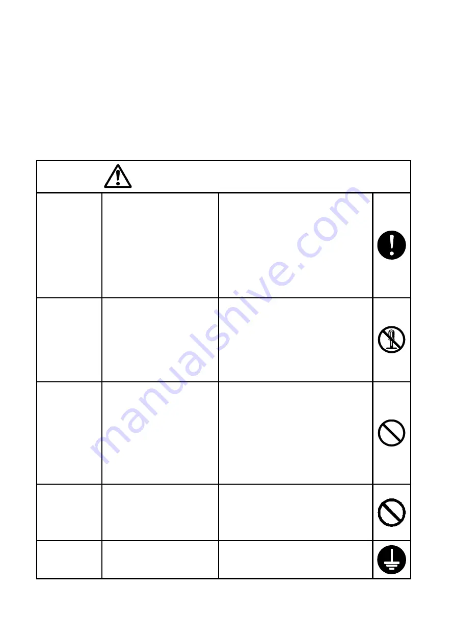


警告 

CAUTION


異常時の 
処置 

Action to take 
against 
abnormal 
situation 

煙が出たり、変な臭いがするな
ど異常が発生したときは、すぐ
に本体のすべてのブレーカー
を切り、供給元電源から切り 
離してください。 
修理は、お買い上げいただいた
販売店もしくは販売会社へ  
ご依頼ください。そのまま使用
すると、感電や火災の原因にな
ります。 

If the Product is fuming or emitting 
odors, immediately turn off the 
breakers on the unit and isolate from 
the main power supply.    Repair 
should be left to the care of your 
SEIKO agent or dealer. If left 
uncorrected, the situation will create 
the potential for electric shock or 
fire. 

分解・修理・


改造の禁止


Prohibition of 
unauthorized 
disassembly, 
repair or 
modification 

修理は、お買い上げいただいた
販売店もしくは販売会社へご
依頼ください。修理技術者以外
の人が分解したり修理・改造を
行うと感電や火災の原因にな
ります。


Tampering or unauthorized repair or 
modification of components may 
adversely affect safety or 
performance of this equipment.   
Failure to follow this instruction may 
lead to a risk of electric shock or fire. 
Repair should be left to the care of 
your SEIKO agent or dealer. 

異物混入禁止


Prohibition of 
allowing 
foreign 
objects in 

製品の内部にピン・金属などの
異物を入れないでください。万
一、これらが内部に混入した 
場合は速やかに電源スイッチ
を切ってください。点検は、  
弊社もしくは代理店にご依頼
ください。そのまま使うと感電
や火災の原因になります。 

Never put any pin, wire, metal piece 
or any other foreign object into a 
hole or gap on purpose or otherwise. 
If a foreign object is allowed into a 
hole or gap by mistake, disconnect 
the main switch, and call your SEIKO 
agent or dealer for inspection and 
servicing. If left uncorrected, this 
hazard creates the potential for 
electric shock or fire. 

電源 

Power supply 

製品仕様で定められた電源以
外は使用しないでください。 
それ以外の電源を使用すると 
感電や火災の原因になります。

Never operate the product on any 
power supply other than specified. If 
left uncorrected, the situation will 
create the potential for electric shock 
or fire. 

アース端子の 
接地 

Earth terminal


製品を誘導障害等から保護す
るため、アース端子は必ず接地
してください。 

Earth terminal should be grounded to 
protect the product from inductive 
disturbance.


Summary of Contents for QC-6M5

Page 1: ...arine Master Clock QC 6M5 Before putting your QC 6M5 to use please be sure to read this manual carefully as it has been prepared to assist in the installation operation and maintenance of your QC 6M5...

Page 2: ...eglect of other reasonable care and servicing due to be done by the owner irrespective of such instructions and failure due to deliberate actions or gross negligence or accident or caused by changes m...

Page 3: ...tion Switches 2 3 Operation NORMAL OPERATION 3 1 Switch the display of UT and LT 3 2 0 SEC ADJUSTMENT 30SEC ADJUSTMENT 3 3 AUTOMATIC TIME ADJUSTMENT 3 4 MANUAL LT ADJUSTMENT 3 5 AUTOMATIC LT ADJUSTMEN...

Page 4: ...fect safety or performance of this equipment Failure to follow this instruction may lead to a risk of electric shock or fire Repair should be left to the care of your SEIKO agent or dealer Prohibition...

Page 5: ...clock to a wall surface with four installation holes Installation dimensions are indicated in Fig 1 6mm dia bolts are suitable Panel mounting type Fix the clock in place with bolts after processing t...

Page 6: ...3 Caution Earth terminal should be grounded as in fig 3 to protect the master clock form inductive interference SECONDARY CLOCKS L N DC24V IN AC IN 85 250 LOGGER AL 24V COM 0 5S OUT COM ADV REV 30S OU...

Page 7: ...heck on polarity of wires connected to the secondary clocks and power supply Synchronize the time of the master clock and the monitor clock to secondary clocks Set the second hand of the master clock...

Page 8: ...ted as two times of the above table The maximum output capacity for 2 hands secondary clock is 1560mA Max 130pcs The maximum output capacity for 3 hands secondary clock is 240mA Max 20pcs The maximum...

Page 9: ...back one input frame or displaying page To decrease the displayed numerals To increase the displayed numerals To forward input frame or displaying page to next To enter the input numerals and the pag...

Page 10: ...isplay In case of RESTART operation it will display the data right before the restart button is pressed The following screen is displayed 0 5sec secondary clock stop Manual adjustment 30sec secondary...

Page 11: ...Minute 00 0 59 5 for Second decimal should be 0 or 5 However any input which does not exist example 30 February is ignored and the leap year is automatically adjusted Please move the cursor to by key...

Page 12: ...llows 0 5sec secondary clock running 30sec secondary clock stop Please push ENTER when the input of LT is correct LT starts Go to the next step To re enter the input move the cursor to by key to get t...

Page 13: ...ime of the hands position is correct 30sec secondary clock starts to move Go to the next step To re enter the input move the cursor to by key to get the former screen During the adjustment the display...

Page 14: ...in 30 seconds OPERATION OF 0 SEC ADJUSTMENT ADJUSTMENT WHEN THE CLOCK LOSES 0 5sec secondary clock running 30sec secondary clock running Under this status when 0 SEC ADJ is pushed it becomes the follo...

Page 15: ...J is pushed it becomes the following display 0 5sec secondary clock adjustment fast moving 30sec secondary clock adjustment fast moving 0 5 sec secondary clocks and 30 sec secondary clocks will be adj...

Page 16: ...rk will be on when it is ready to receive a signal from GPS unit Automatic TIME adjustment by GPS to the internal clock is to be executed once a day from the time of 23 30 00 to 23 50 00 UT on the mas...

Page 17: ...play to LT by At the display on LT push 20 After the above operation push 1 five times The display of PUSH and ENTER is alternately displayed at cycle of one second Push key 30 sec secondary clocks wi...

Page 18: ...ustment located on the Printed Circuit Board LT on the master clock will be automatically adjusted in accordance with the time of LT from an external GPS unit Before Automatic LT Adjustment The ship m...

Page 19: ...owing displays Each status of the illumination the AC power supply and the DC power supply is displayed from the left end The display changes as follows when the DIMMER key is pushed within five secon...

Page 20: ...LCD simultaneously 4 1 4 1 RESUMED FROM POWER FAILURE When the power is resumed from failure it becomes the following display The ALARM lamp blinks every second The output line will be the following s...

Page 21: ...splayed Display of abnormal status and the current time is alternately displayed at interval of one second The ALARM lamp blinks every second as well Each output line will be the following status 0 5s...

Page 22: ...ay of abnormal status and the current time is alternately displayed at interval of one second The ALARM lamp blinks every second as well Each output line will be the following status 0 5sec secondary...

Page 23: ...d logger signal are output via circuit of Transistor open collector Sample of connection 100mA 150mA DC24V 5V Output Voltage less than 100mA ALARM less than 150mA LOGGER Relay Relay contact Arc exting...

Page 24: ...After fixing the cause push RESTART key 0 5sec secondary clock and 30sec secondary clock are not synchronized Wrong operation of time synchronization Operate correctly Tripping of DC NFB Overload Sho...

Page 25: ...25 I 5321 4 EXTERNAL VIEW...

Page 26: ...26 I 5321 4 MASTER SECONDARY RS 422 NMEA0183 RS 422 NMEA0183 RS 232C...

Page 27: ...wired system RS 422 One port Based on NMEA0183 Logger signal output Five wired system One port 150mA or less in total 24V COMMON 30 second polarized pulse output 30 second polarized pulse output Signa...

Page 28: ...N HUGHES NETHERLANDS LTD Klompenmarkerstraat 64 3194 DC Hoogvlit Rotterdam The Netherlands Tel 31 10 4167622 Fax 31 10 4167218 Telex 26545 OBMAR NL KELVIN HUGHES LTD New North Road Hainault Ilford Ess...

Page 29: ......

Page 30: ...I 5321 4 URL http www seiko sts co jp...

Reviews: