background image

6


I-5321-4


2.電源・子時計との結線 

2.

WIRING TO POWER SUPPLY AND 


①  取付前に全ての子時計の針を同一時刻


(例えば12時0分0秒)

に合わせます。


Before installation, synchronize all secondary 

clocks. (Ex.12hr 0min 0sec)


② 入線穴の選択


親時計は背面および下面に入線穴があり下

面にかくし板が取付けてあります。

入線穴と

して下面を利用する場合は、かくし板を背面

に移してください


Selection of service inlet 

The master clock is provided with two service 

inlets on the back and bottom. The bottom inlet is 

blocked with a blank panel.   

When using the bottom inlet, relocate the blank 

panel to the back inlet.
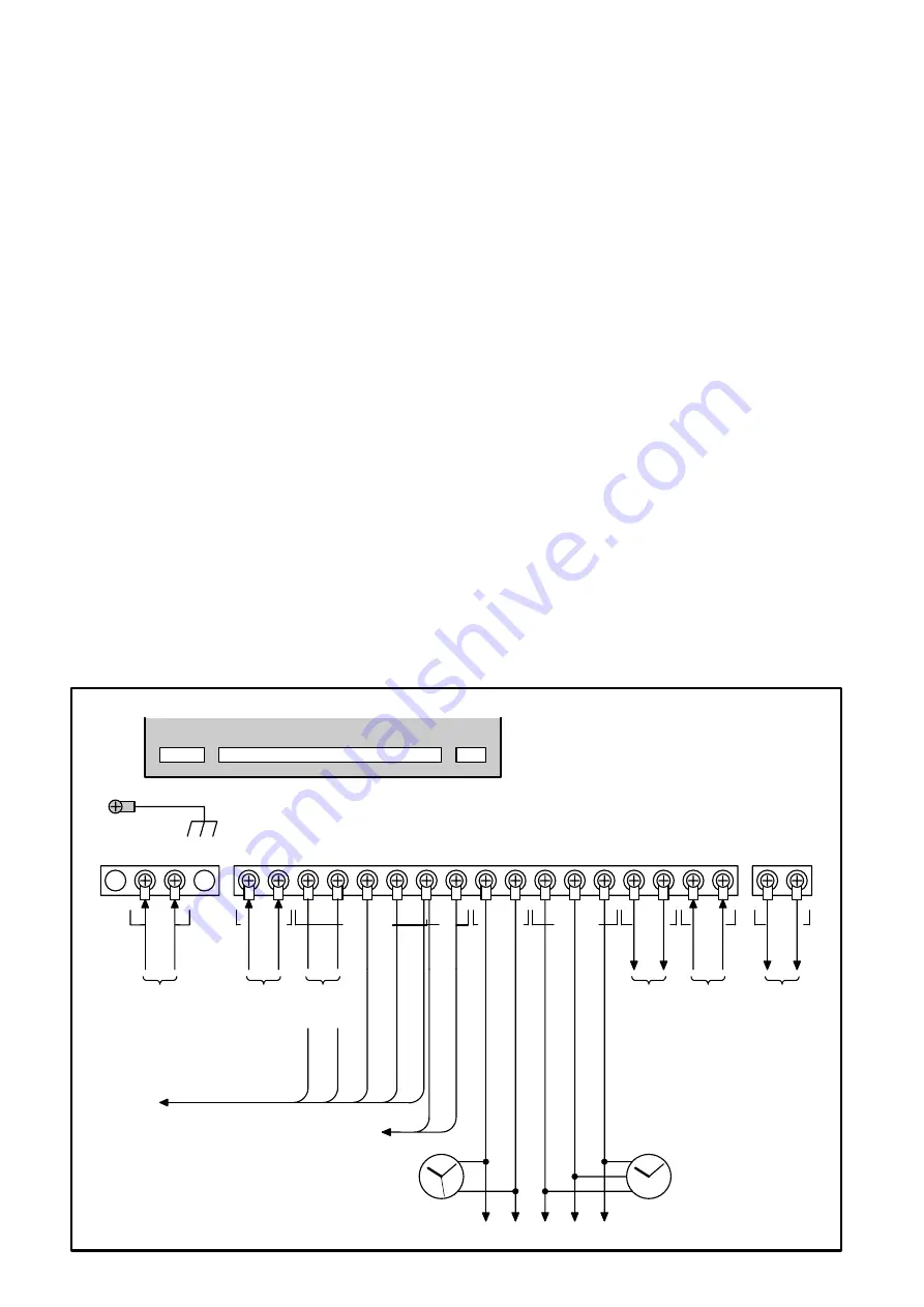
 

③ 結線 

扉ネジ2カ所をゆるめ扉を開けて、

  内部右

下の端子板に結線します。結線に際しては圧

着工具が必要です。圧着端子は付属のものを

ご使用ください。Fig.3 の通り正確に行って

ください。 


注)親時計を誘導障害等から保護する 

ため、下図のアース端子を用い、必ず接地し

て下さい。


Wiring


Loosen the panel screws and open the panel. 

Connect wires to the terminal block located on 

the lower, right side of the clock with clamping 

tools Be sure to use the clamp terminals provided 

for connecting wires. Correctly connect the wires 

according to Fig.3. 

Caution


Earth terminal should be grounded


as in fig.3 to 

protect the master clock form inductive interference.


SECONDARY CLOCKS


L

N

DC24V IN

AC IN
85-250

+

-

LOGGER

AL

-

24V
COM

0.5S OUT

+

-

COM ADV

REV

30S OUT

RS-422

OUT

RS-422

IN

+

-

+

-

RS-232C

OUT

+

-

30S+ 30S

-

AC85V

AC250V

DC24V

±10%

30

秒有極

30sec.
polarized


(-)

O

u

tp
ut
d

u

rin

g
rev
.

tu

rn

ing(
-

)(

R

E

V

)

調


(-)

O

u

tp

u

t

dur

in

g
h

an
d

a

d

ju

s

tin

g

(-

)(

A

D

J

)


(+)

24V

2

4

V
C

o

mmo

n

(+
)

ロガー

Logger

最大出力容量

150mA

Max. output capacity


(+)(-)

Al
a

rm

DC24V

デジタル信号出力

R

S

-

422

D

ig

ita

l

S

igna

l

O

ut
put

(+)

(-)

(+)

(-)

(+)

(-)

(+)

(-)

デジタル信号入力

R

S

-

422

D

igi

ta

l

S

igna

l

Inp
ut

デジタル信号出力

R

S

-

232

C

D

ig

ita

l

S

igna

l

O

ut
put

(+)

(-)

オプショ

Op

tio

n

30

秒子時計

30sec.leap secondary
clocks

0.5

秒子時計

0.5sec.leap secondary
clocks

A,B,C

を合わせる

Set A,B and C

,

を合わせる

Set

and

TB1

TB3

TB2

基板

Printed Circuit Board

TB1

TB3

TB2

アース端子

Earth terminal

0.5

秒子時計

Î

最大出力容量

240mA

(

20

台)

30

秒子時計

Î

最大出力容量

1560mA

(

130

台)

0.5 sec secondary clocks

Î

Maximum capacity 240mA(20pcs)

30 sec secondary clocks

Î

Maximum capacity 1560mA(130pcs)

Fig.3.

A

C

B

A

C

B

(+)

(-)

(+)

(-)

Summary of Contents for QC-6M5

Page 1: ...arine Master Clock QC 6M5 Before putting your QC 6M5 to use please be sure to read this manual carefully as it has been prepared to assist in the installation operation and maintenance of your QC 6M5...

Page 2: ...eglect of other reasonable care and servicing due to be done by the owner irrespective of such instructions and failure due to deliberate actions or gross negligence or accident or caused by changes m...

Page 3: ...tion Switches 2 3 Operation NORMAL OPERATION 3 1 Switch the display of UT and LT 3 2 0 SEC ADJUSTMENT 30SEC ADJUSTMENT 3 3 AUTOMATIC TIME ADJUSTMENT 3 4 MANUAL LT ADJUSTMENT 3 5 AUTOMATIC LT ADJUSTMEN...

Page 4: ...fect safety or performance of this equipment Failure to follow this instruction may lead to a risk of electric shock or fire Repair should be left to the care of your SEIKO agent or dealer Prohibition...

Page 5: ...clock to a wall surface with four installation holes Installation dimensions are indicated in Fig 1 6mm dia bolts are suitable Panel mounting type Fix the clock in place with bolts after processing t...

Page 6: ...3 Caution Earth terminal should be grounded as in fig 3 to protect the master clock form inductive interference SECONDARY CLOCKS L N DC24V IN AC IN 85 250 LOGGER AL 24V COM 0 5S OUT COM ADV REV 30S OU...

Page 7: ...heck on polarity of wires connected to the secondary clocks and power supply Synchronize the time of the master clock and the monitor clock to secondary clocks Set the second hand of the master clock...

Page 8: ...ted as two times of the above table The maximum output capacity for 2 hands secondary clock is 1560mA Max 130pcs The maximum output capacity for 3 hands secondary clock is 240mA Max 20pcs The maximum...

Page 9: ...back one input frame or displaying page To decrease the displayed numerals To increase the displayed numerals To forward input frame or displaying page to next To enter the input numerals and the pag...

Page 10: ...isplay In case of RESTART operation it will display the data right before the restart button is pressed The following screen is displayed 0 5sec secondary clock stop Manual adjustment 30sec secondary...

Page 11: ...Minute 00 0 59 5 for Second decimal should be 0 or 5 However any input which does not exist example 30 February is ignored and the leap year is automatically adjusted Please move the cursor to by key...

Page 12: ...llows 0 5sec secondary clock running 30sec secondary clock stop Please push ENTER when the input of LT is correct LT starts Go to the next step To re enter the input move the cursor to by key to get t...

Page 13: ...ime of the hands position is correct 30sec secondary clock starts to move Go to the next step To re enter the input move the cursor to by key to get the former screen During the adjustment the display...

Page 14: ...in 30 seconds OPERATION OF 0 SEC ADJUSTMENT ADJUSTMENT WHEN THE CLOCK LOSES 0 5sec secondary clock running 30sec secondary clock running Under this status when 0 SEC ADJ is pushed it becomes the follo...

Page 15: ...J is pushed it becomes the following display 0 5sec secondary clock adjustment fast moving 30sec secondary clock adjustment fast moving 0 5 sec secondary clocks and 30 sec secondary clocks will be adj...

Page 16: ...rk will be on when it is ready to receive a signal from GPS unit Automatic TIME adjustment by GPS to the internal clock is to be executed once a day from the time of 23 30 00 to 23 50 00 UT on the mas...

Page 17: ...play to LT by At the display on LT push 20 After the above operation push 1 five times The display of PUSH and ENTER is alternately displayed at cycle of one second Push key 30 sec secondary clocks wi...

Page 18: ...ustment located on the Printed Circuit Board LT on the master clock will be automatically adjusted in accordance with the time of LT from an external GPS unit Before Automatic LT Adjustment The ship m...

Page 19: ...owing displays Each status of the illumination the AC power supply and the DC power supply is displayed from the left end The display changes as follows when the DIMMER key is pushed within five secon...

Page 20: ...LCD simultaneously 4 1 4 1 RESUMED FROM POWER FAILURE When the power is resumed from failure it becomes the following display The ALARM lamp blinks every second The output line will be the following s...

Page 21: ...splayed Display of abnormal status and the current time is alternately displayed at interval of one second The ALARM lamp blinks every second as well Each output line will be the following status 0 5s...

Page 22: ...ay of abnormal status and the current time is alternately displayed at interval of one second The ALARM lamp blinks every second as well Each output line will be the following status 0 5sec secondary...

Page 23: ...d logger signal are output via circuit of Transistor open collector Sample of connection 100mA 150mA DC24V 5V Output Voltage less than 100mA ALARM less than 150mA LOGGER Relay Relay contact Arc exting...

Page 24: ...After fixing the cause push RESTART key 0 5sec secondary clock and 30sec secondary clock are not synchronized Wrong operation of time synchronization Operate correctly Tripping of DC NFB Overload Sho...

Page 25: ...25 I 5321 4 EXTERNAL VIEW...

Page 26: ...26 I 5321 4 MASTER SECONDARY RS 422 NMEA0183 RS 422 NMEA0183 RS 232C...

Page 27: ...wired system RS 422 One port Based on NMEA0183 Logger signal output Five wired system One port 150mA or less in total 24V COMMON 30 second polarized pulse output 30 second polarized pulse output Signa...

Page 28: ...N HUGHES NETHERLANDS LTD Klompenmarkerstraat 64 3194 DC Hoogvlit Rotterdam The Netherlands Tel 31 10 4167622 Fax 31 10 4167218 Telex 26545 OBMAR NL KELVIN HUGHES LTD New North Road Hainault Ilford Ess...

Page 29: ......

Page 30: ...I 5321 4 URL http www seiko sts co jp...

Reviews: