


TECHNICAL GUIDE
Cal. V157A/V158A
0/8
ql
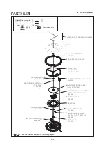
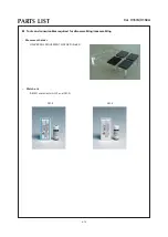
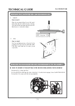
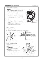
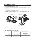
RECHARGEABLE BATTERY UNIT
• How to remove
Remove the battery lead terminal screw, and then
pry up the “A” portion in the illustration with tweezers
to remove the rechargeable battery unit.
• How to install
Set the “B” portion of the battery lead terminal to the
guide hole of the main plate, and then push the center
portion of the rechargeable battery unit (the “C”
portion in the illustration) to fix it in position.
Battery lead terminal
Notes:
• Be sure to observe the correct polarity of the
rechargeable battery unit. The (-) side has the lead
terminal.
• Handle the rechargeable battery unit with care so
as not to short-circuit its (+) and (-) terminals.
“c” portion
rechargeable battery unit
wd
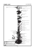
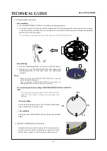
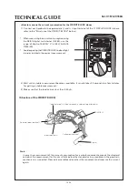
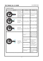
TRAIN WHEEL BRIDGE
fourth wheel and pinion
minute wheel
Refer to the illustrations below to check where to install the respective wheels.
step rotor
third wheel and pinion
setting wheel
fifth wheel and pinion
step rotor
fourth wheel and pinion
fifth wheel and pinion third wheel and pinion
minute wheel
setting wheel
e;
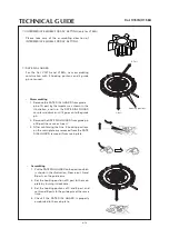
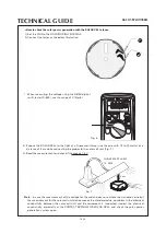
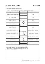
TRAIN WHEEL SETTING LEVER
ef
SETTING LEVER
eg
YOKE
• Setting position
Refer to the illustration at right.
setting lever
• Setting position
yoke
train wheel setting lever
center wheel and pinion
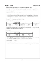
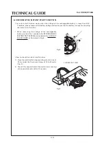
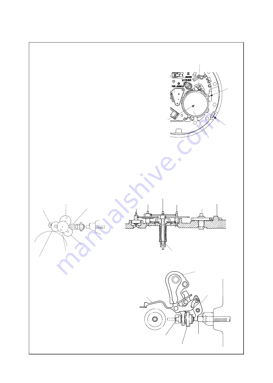
“B” portion
“a” portion
The date corrector wheel has some elasticity
in the contact with the winding stem so that
it can be easily fixed.
Push in the winding stem straight toward
the center of the main plate.
eh
SETTING STEM
winding stem
date corrector wheel
clutch wheel


