
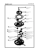
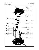
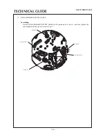
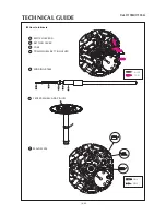
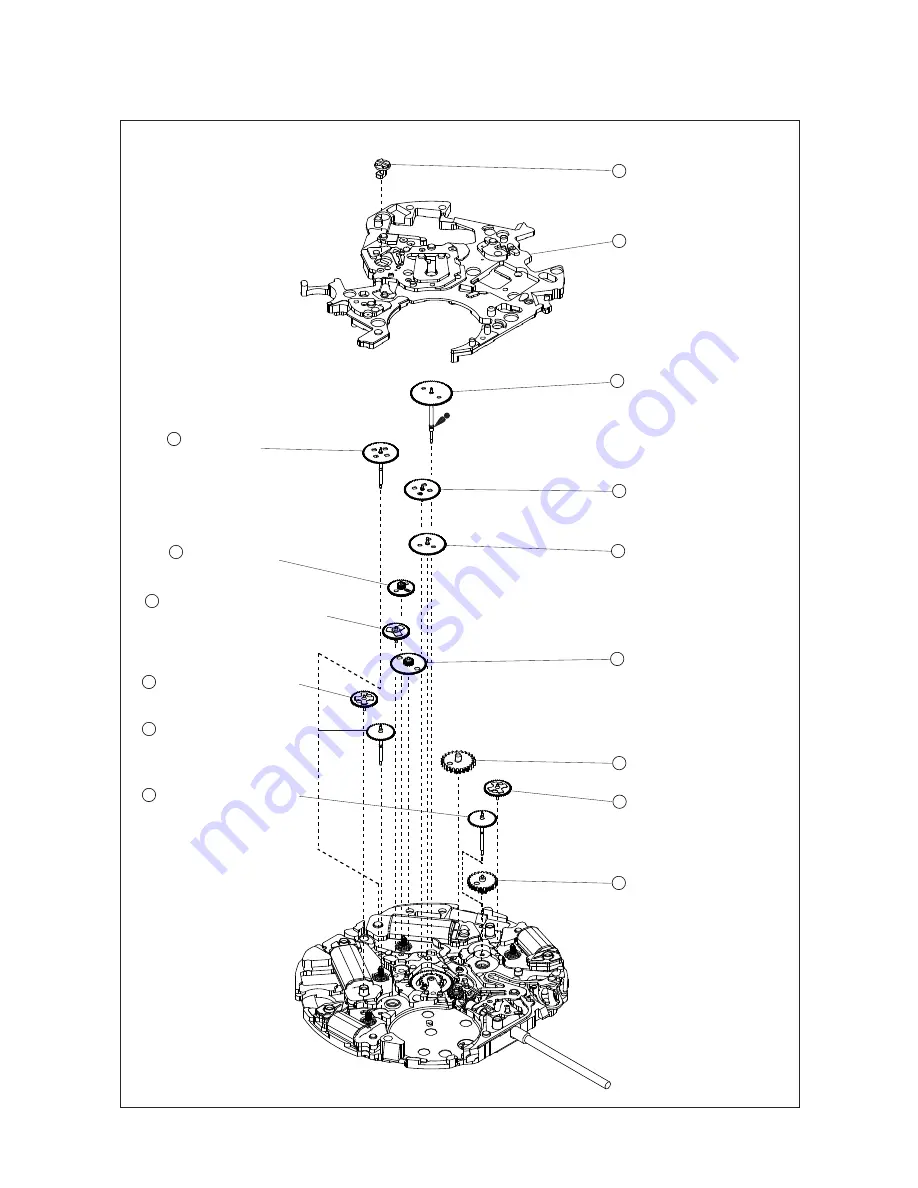
45 CENTER WHEEL FOR
ALARM
0902 502
42 MINUTE COUNTING WHEEL
0902 500
41 INTERMEDIATE MINUTE
COUNTING WHEEL
0950 590
39 FIRST INTERMEDIATE
SESOND COUNTING WHEEL
0885 590
32 PIN FOR TRAIN WHEEL
BRIDGE
0027 974
33 TRAIN WHEEL BRIDGE
0125 516
34 1/5-SECOND COUNTING
WHEEL
0888 501
36 FORTH WHEEL AND PINION
0241 583
37 THIRD WHEEL AND PINION
0231 580
40 SECOND INTERMEDIATE
1/5-SECOND COUNTING
WHEEL
0885 591
43 MINUTE WHEEL
0261 582
46 ALRAM MINUTE WHEEL
0261 582
35 SMALL SECOND WHEEL
0240 511
44 INTERMEDIATE ALARM
WHEEL
0950 590
38 FIFTH WHEEL AND PINION
0701 581
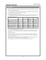
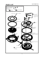
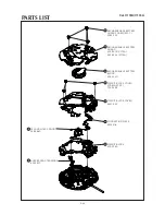
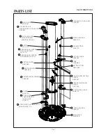
Cal. V172A/V174A
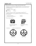
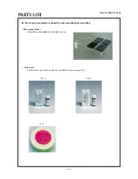
PARTS LIST
6/24


