Electronics
Installation Instruction UK
-
Page 5
Please unplug power-supply cable before changing any connection!
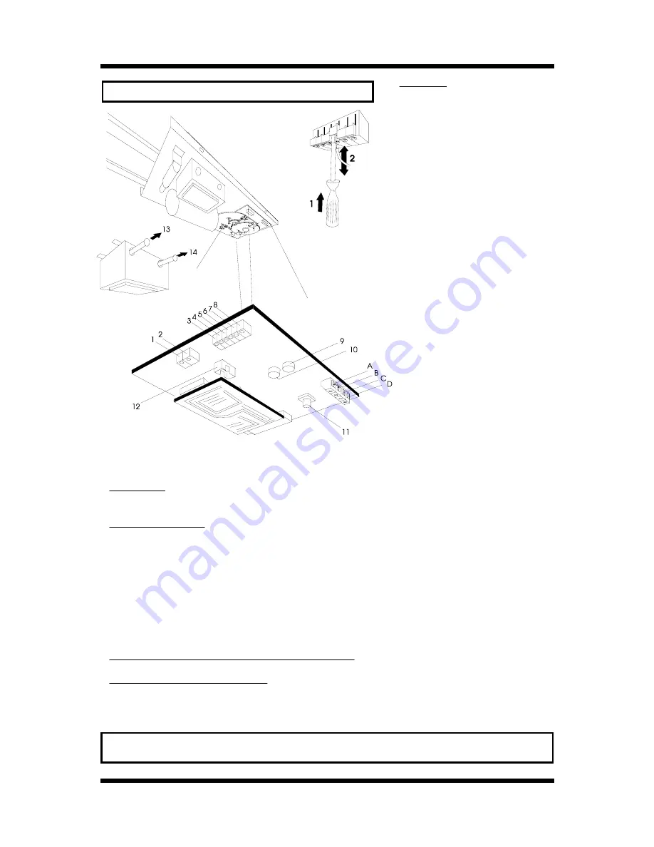
The most important connections for the installation are:
Test-button
for running the operator without remote-control:
11
First push: OPENING, second push: STOP, third push: CLOSING and so on.
Regulation of force:
CLOSING force:
9
OPENING force:
10
The force for either OPENING or CLOSING can be adjusted seperately.
Adjustement of the force: turn down the forces to their minimum. When you let the mounted operator run, it
then probably will switch off because it cannot move the garage door. Then rise the force steadily till it is high
enough to move the door. Do not adjust the forces on their maximum
if not necessary for door movement! The excess force will increase the damage on objects or persons being
accidentially hit by the garage door (if there is no external security connected)!
(Turning to the right rises the force, turning to the left decreases the force).
Connection for external push-button or key switch:
C
and
D
Connection for external security:
A
and
B
Here you can connect a light barrier or a security contact.
Do not remove the bridge
between A and B
if you
do not connect an external security!
This is a NC-contact: if the bridge is removed, the operator will not
work.
Do not put any electrical tension from outside onto the electric board!
That would damage the circuit board heavily!
Connections:
1 : Lighting (blue)
2 : "
(blue)
UK 80+UK 100
:
3 : 22or 28 V AC, dependend on speed
setting
4 : "
UK 60:
3: 24 V AC
4: "
5 : Motor
(black or green)
6 : "
(red)
7 : Transformer
(brown or white)
8 : "
(green/yellow)
9 : CLOSING Force
10 : OPENING For ce
11 : Test-button (OPEN-STOP-CLOSE)
12 : Connection for the limit-switch MBX cable
13 : Primary fuse, 230 V AC, T 1 Amp
14 : Secondary fuse, T 6,3 Amp
A : Connection for external security (light
barriere), potential free
B : Connection for external security (light
barriere)
C : Connection for push-button, potential free
D : "
Summary of Contents for UK 100
Page 9: ...Problems No problem...


