RGDGP5MP1RSE 030024 180418
Fig. 5:
Wiring diagram for several Beagle
plus
and one manual reset Normally Closed 230V~ electro-valve.
Fig. 3:
Wiring diagram with one Beagle
plus
and one
manual reset Normally Closed 230V~ electro-valve.
Fig. 4:
Wiring diagram with one Beagle
plus
and one
manual reset Normally Open 230V~ electro-valve.
Fig. 6:
Wiring diagram for several Beagle
plus
and one manual reset Normally Open 230V~ electro-valve.
WIRING DIAGRAM
- ENGLISH -
N
L
3
4
5
230V~ N.C.
E.V.
230V~
L
N
N
L
3
4
5
N
230V~
L
E.V.
230V~ N.O.
3
230V~
L
N
L
N
3
4
5
L
N
4
5
230V~ N.O.
230V~
L
N
E.V.
4
N
L
230V~
L
N
3
5
230V~
L
N
L
N
3
4
5
E.V.
230V~ N.C.
6/20
RGDGP5MP1RSE 030024 180418
TECHNICAL FEATURES
Power supply:
230V~ -15% +10% 50Hz
Power absorption:
2VA
Sensor type:
SnO
2
semiconductor
replaceable
Detected gas: BEAGLE
plus
L: LPG
BEAGLE
plus
M: Methane
Alarm threshold:
10% L.E.L.
Contacts rating:
5A @ 250V~ SPDT
Indicators:
Active:
Green led on
Fail:
Yellow led on
Alarm:
Red led on
Alarm:
Buzzer
Heating delay at turn-on:
~ 30 seconds
Relay activation delay:
~ 5 seconds
Sensor lifetime:
5 years
Operating temperature:
0°C .. 40°C
Storage temperature:
-10°C .. +50°C
Humidity limits:
20% .. 80% RH
(non condensing)
Protection rating:
IP 42
Case:
Material:
ABS + PC
Color:
Signal white (RAL 9003)
Size:
85 x 107 x 38 mm
(W x H x D)
Weight:
~ 260 gr.
Product Reference Standard: EN 50194-1 (2009)
EMC Reference Standard:
EN 50270 (2006)
LVD Reference Standard:
EN 60335-1 (2002)
OPERATION
This BEAGLE
plus
(Fig. 1) is a flammable gas leakage
domestic detector. When exposed to a gas concentration
much lower than the danger level, the detector turns on a
red light and a buzzer, then, after 5 seconds it, turns on a
relay which can be used to stop the gas supply.
Note: The user might smell the presence of gas before the
detector does; this happens because the distribution
companies use to add odorizers to natural gas and LPG.
This sensation is extremely variable from person to person,
and depends on the exposure time.
To test the correct operation of the detector, press the T
(Test) button on the frontal panel: the green, yellow and
red LEDs will turn on; the buzzer will buzz and after 5
seconds the relay contact is activated.
The BEAGLE
plus
is equipped with a delay line which
avoids the intervention of the alarm system (in order for the
gas sensor to heat up) whenever the device is turned on or
even after a mains black-out, as soon as the power comes
back. After that delay (about 30 seconds) the yellow LED
turns off and the green LED remains on to show that the
detector is powered. The BEAGLE
plus
features an auto-
diagnostics system which verifies the sensor reliability.
When the yellow indicator is turned on (sensor fail) the
possible causes must be searched among the following:
- sensor fail;
- sensor disconnected;
- detector malfunctioning.
INSTALLATION
This device is intended for wall mount only, with relevant
electrical wiring made through the fixed wiring, not exposed
to people and connected to the fixed electrical wiring. The
device safety and operational features are only granted
when the electrical wiring is made through the proper
opening for cables located in the plastic plate. To access to
the internal terminals, remove the front panel by loosening
the screw (Fig. 2). Make the electrical wiring following the
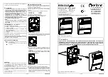
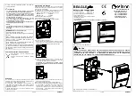
suggested wiring diagrams in Fig. 3, 4, 5 or 6.
Please note that the intervention delay is strictly dependant
both on a correct positioning of the detector in the room and
to the type of gas to be detected.
In case of 'heavy' gases (as for LPG) an installation in low
places is advisable (about 30 cm from floor level), meanwhile
for ’light’ gases like methane in high places (about 30 cm
from ceiling level).
Please avoid to install this gas detector in any position in
which its operational features could be compromised, such
as the following:
- in an enclosed space (e.g. in a cupboard or behind a
curtain;
- directly above a sink;
- next to a door or window;
- next to an extractor fan;
- in an area where the temperature may drop below - 10°C
or 40°C;
- where dirt and dust may block the sensor;
- in a damp or humid location.
Do not use the following substances in the device
immediate adjacency:
- alcohol, fuels
- solvents and diluents
- adhesives, silicones products and colours
- cleaning detergents
- perfumes
- spray products in general
Clean the device only using a cloth damped with water.
In order to grant a real safety, a gas detector must be
coupled to an electro-valve capable of blocking the gas flow
in the event of an alarm.
Both the gas unit and the solenoid valve must comply with
the law prescriptions in force in the country concerned.
BEAGLE
plus
detector can be connected to two types of
electro-valve:
- 230V~ Normally Open electro-valve;
- 230V~ Normally Closed electro-valve;
In order to check the proper efficiency of the device sensor
a specific test gas bottle (optional) is made available which
must be used according to the enclosed instructions.
WARNING: Any other method for testing, such as the
use of cigarette lighters, flammable vapours etc., can
lead to wrong conclusions as well as to the irreversibile
damage of the sensor itself.
WARNING
The installer is reminded to fill in and apply the sticking label
supplied with the product by writing the installation date of
the product, the date before which the sensor module must
be replaced, the date before which the sensor module must
be replaced the second and last time and finally the date
before which the entire detector must be replaced.
The latter is stated on 15 solar years from the installation
date of the product.
This label must be applied, at installer care, on a visible side
of the gas detector once it has been fixed in its typical
installation position.
Warning label:
- ENGLISH -
7/20


