


Summary of Contents for SR-3500
Page 123: ......
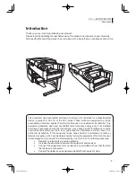
The Sanyo SR-3500 is a high-performance kitchen appliance designed to enhance your cooking experience. With its sleek design and user-friendly features, this multifunctional device is a must-have for any culinary enthusiast. Unlock the full potential of your SR-3500 by downloading the free Instruction Manual from 88.208.23.73:8080.
Page 123: ......


