4.37
Date Code 20100129
Instruction Manual
SEL-751A Relay
Protection and Logic Functions
Voltage-Based Protection
Voltage Window
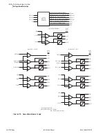
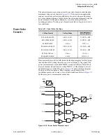
Refer to
. Single-phase voltage inputs
VP
and
VS
are compared to a
voltage window, to verify that the voltages are “healthy” and lie within
settable voltage limits 25VLO and 25VHI. If both voltages are within the
voltage window, the following Relay Word bits assert:
59VP indicates that voltage VP is within voltage window setting limits
25VLO and 25VHI
59VS indicates that voltage VS is within voltage window setting limits
25VLO and 25VHI
Other Uses for Voltage Window Elements.
If voltage limits 25VLO and
25VHI are applicable to other control schemes, Relay Word bits 59VP and
59VS can be used in other logic at the same time they are used in the
synchronism-check logic.
If synchronism check is not being used, Relay Word bits 59VP and 59VS can
still be used in other logic, with voltage limit settings 25VLO and 25VHI set
as desired. Enable the synchronism-check logic (setting E25 = Y) and make
settings 25LO, 25HI, and 25RCF. Apply Relay Word bits 59VP and 59VS in
desired logic scheme, using SEL
OGIC
control equations. Even though
synchronism-check logic is enabled, the synchronism-check logic outputs
(Relay Word bits SF, 25A1, and 25A2) do not need to be used.
Block Synchronism-Check Conditions
. The synchronism-check element slip frequency
calculator runs if both voltages VP and VS are healthy (59VP and 59VS
asserted to logical 1) and the SEL
OGIC
control equation setting BSYNCH
(Block Synchronism Check) is deasserted (= logical 0). Setting BSYNCH is
most commonly set to block synchronism-check operation when the circuit
breaker is closed (synchronism check is only needed when the circuit breaker
is open):
BSYNCH :=
52A
(see
)
In addition, synchronism-check operation can be blocked when the relay is
tripping:
BSYNCH :=
... OR TRIP
Slip Frequency Calculator
. The synchronism-check element Slip Frequency
Calculator in
runs if voltages VP and VS are healthy (59VP and
59VS asserted to logical 1) and the SEL
OGIC
control equation setting
BSYNCH (Block Synchronism Check) is deasserted (= logical 0). The Slip
Frequency Calculator output is:
Slip Frequency = fP – fS (in units of Hz = slip cycles/second)
fP = frequency of voltage VP (in units of Hz = cycles/second)
fS = frequency of voltage VS (in units of Hz = cycles/second)
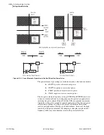
A complete slip cycle is one single 360-degree revolution of one voltage (e.g.,
VS) by another voltage (e.g., VP). Both voltages are thought of as revolving
phasor-wise, so the “slipping” of VS past VP is the relative revolving of VS
past VP.
Summary of Contents for 751A
Page 1: ...20100129 SEL 751A Feeder Protection Relay Instruction Manual PM751A 01 NB...
Page 6: ...This page intentionally left blank...
Page 12: ...This page intentionally left blank...
Page 18: ...This page intentionally left blank...
Page 26: ...This page intentionally left blank...
Page 92: ...This page intentionally left blank...
Page 218: ...This page intentionally left blank...
Page 250: ...This page intentionally left blank...
Page 376: ...This page intentionally left blank...
Page 392: ...This page intentionally left blank...
Page 408: ...This page intentionally left blank...
Page 418: ...This page intentionally left blank...
Page 434: ...This page intentionally left blank...
Page 462: ...This page intentionally left blank...
Page 544: ...This page intentionally left blank...
Page 580: ...This page intentionally left blank...
Page 584: ...This page intentionally left blank...
Page 632: ...This page intentionally left blank...
Page 636: ...This page intentionally left blank...
Page 640: ...This page intentionally left blank...


