4.81
Date Code 20100129
Instruction Manual
SEL-751A Relay
Protection and Logic Functions
Logic Settings (SET L Command)
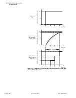
Time = 15 Minutes
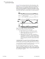
The three five-minute intervals in the sliding time-window at “Time = 15
minutes” each integrate into the following 5-minute totals:
Rolling demand meter response at “Time = 15 minutes” = 3.0/3 = 1.0 per unit.
Logic Settings (SET L Command)
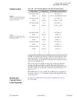
Settings associated with latches, timers, counters, math variables, and output
contacts are listed below.
SEL
OGIC
Enables
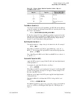
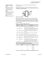
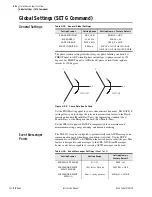
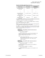
The following table shows the enable settings for latch bits (ELAT), SEL
OGIC
control equations (including timers) (ESV), Counters (ESC), and math
variable equations (EMV). This helps limit the number of settings that you
need to make. For example, if you need six timers, only enable six timers.
Latch Bits
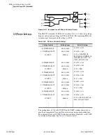
Latch control switches (latch bits are the outputs of these switches) replace
traditional latching devices. Traditional latching devices maintain output
contact state. The SEL-751A latch control switch also retains state even when
power to the device is lost. If the latch control switch is set to a programmable
output contact and power to the device is lost, the state of the latch control
switch is stored in nonvolatile memory, but the device de-energizes the output
contact. When power to the device is restored, the programmable output
contact will go back to the state of the latch control switch after device
initialization. Traditional latching device output contact states are changed by
pulsing the latching device inputs (see
). Pulse the set input to
close (set) the latching device output contact. Pulse the reset input to open
(reset) the latching device output contact. The external contacts wired to the
latching device inputs are often from remote control equipment (e.g., SCADA,
RTU).
Five-Minute Totals
Corresponding Five-Minute Interval
1.0 per unit
0 to 5 minutes
1.0 per unit
5 to 10 minutes
1.0 per unit
10 to 15 minutes
3.0 per unit
Table 4.31
Enable Settings
Setting Prompt
Setting Range
Default Setting
SEL
OGIC
Latches
N, 1–32
ELAT := 4
SV/Timers
N, 1–32
ESV := 5
SEL
OGIC
Counters
N, 1–32
ESC := N
Math Variables
N, 1–32
EMV := N
Summary of Contents for 751A
Page 1: ...20100129 SEL 751A Feeder Protection Relay Instruction Manual PM751A 01 NB...
Page 6: ...This page intentionally left blank...
Page 12: ...This page intentionally left blank...
Page 18: ...This page intentionally left blank...
Page 26: ...This page intentionally left blank...
Page 92: ...This page intentionally left blank...
Page 218: ...This page intentionally left blank...
Page 250: ...This page intentionally left blank...
Page 376: ...This page intentionally left blank...
Page 392: ...This page intentionally left blank...
Page 408: ...This page intentionally left blank...
Page 418: ...This page intentionally left blank...
Page 434: ...This page intentionally left blank...
Page 462: ...This page intentionally left blank...
Page 544: ...This page intentionally left blank...
Page 580: ...This page intentionally left blank...
Page 584: ...This page intentionally left blank...
Page 632: ...This page intentionally left blank...
Page 636: ...This page intentionally left blank...
Page 640: ...This page intentionally left blank...


