4.94
SEL-751A Relay
Instruction Manual
Date Code 20100129
Protection and Logic Functions
Synchrophasor Measurement
Group Selection
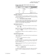
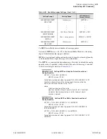
The TGR setting defines the amount of time that the SS1, SS2, and SS3
SEL
OGIC
control equation logic results must remain stable before the relay
enables a new setting group. Typically, a one-second delay is sufficient.
SS1, SS2, and SS3 are SEL
OGIC
control equations that help define when
setting Group 1, 2, and 3 are active. With the settings shown above, SS1 is set
equal to logical 1, thus setting Group 1 always is active.
Synchrophasor Measurement
The SEL-751A relay provides Phasor Measurement Control Unit (PMCU)
capabilities when connected to an IRIG-B time source. See
for description and
for the settings.
Breaker Failure Setting
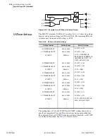
The SEL-751A provides flexible breaker failure logic (see
). In the
default breaker failure logic, assertion of Relay Word bit TRIP starts the BFD
timer if the sum of positive-sequence and negative-sequence currents is above
0.02 • I
NOM
. If the current remains above the threshold for BFD delay setting,
Relay Word bit BFT will assert. Use the BFT to operate an output relay to trip
appropriate backup breakers.
Changing the BFI and/or 52ABF settings can modify the default breaker
failure logic.
➤
Set BFI = R_TRIG TRIP AND NOT IN102 if input
IN102
is
manual trip only and breaker failure initiation is not desired
when the tripping is caused by this input.
➤
Set 52ABF = Y if you want the breaker failure logic to detect
failure of breaker/contactor auxiliary contact to operate during
the trip operation as defined by the BFI setting.
Table 4.41
Setting Group Selection
Setting Prompt
Setting Range
Setting Name :=
Factory Default
GRP CHG DELAY
0–400 sec
TGR := 3
SELECT GROUP1
SEL
OGIC
SS1 := 1
SELECT GROUP2
SEL
OGIC
SS2 := 0
SELECT GROUP3
SEL
OGIC
SS3 := 0
Table 4.42
Breaker Failure Setting
Setting Prompt
Setting Range
Setting Name :=
Factory Default
52A INTERLOCK
Y, N
52ABF := N
BK FAILURE DELAY
0.00–2.00 sec
BFD := 0.50
BK FAIL INITIATE
SEL
OGIC
BFI := R_TRIG TRIP
Summary of Contents for 751A
Page 1: ...20100129 SEL 751A Feeder Protection Relay Instruction Manual PM751A 01 NB...
Page 6: ...This page intentionally left blank...
Page 12: ...This page intentionally left blank...
Page 18: ...This page intentionally left blank...
Page 26: ...This page intentionally left blank...
Page 92: ...This page intentionally left blank...
Page 218: ...This page intentionally left blank...
Page 250: ...This page intentionally left blank...
Page 376: ...This page intentionally left blank...
Page 392: ...This page intentionally left blank...
Page 408: ...This page intentionally left blank...
Page 418: ...This page intentionally left blank...
Page 434: ...This page intentionally left blank...
Page 462: ...This page intentionally left blank...
Page 544: ...This page intentionally left blank...
Page 580: ...This page intentionally left blank...
Page 584: ...This page intentionally left blank...
Page 632: ...This page intentionally left blank...
Page 636: ...This page intentionally left blank...
Page 640: ...This page intentionally left blank...


