5.6
SEL-751A Relay
Instruction Manual
Date Code 20100129
Metering and Monitoring
Metering
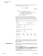
To reset energy meter values, issue the
METER RE
command as shown in
.
=>>
MET RE <Enter>
Reset Metering Quantities (Y,N)?
Y <Enter>
Reset Complete
=>>
Figure 5.5
Device Response to the METER RE Command
Maximum and
Minimum Metering
Maximum and minimum metering allows you to determine maximum and
minimum operating quantities such as currents, voltages, power, analog input
quantities, RTD quantities and frequency.
metering quantities.
All maximum and minimum metering values will have the date and time that
they occurred. The analog quantities from
are checked
approximately every 0.5 seconds and, if a new maximum or minimum value
occurs, this value is saved along with the date and time that the maximum or
minimum value occurred. Maximum and minimum values are only checked if
relay element FAULT is deasserted (no fault condition exists) for at least one
second.
Additionally, the following minimum thresholds must also be met:
➤
Current values I
A
, I
B
, I
C
, and I
N
: 3% of the nominal CT rating.
➤
Current value I
G
: I
A
, I
B
, and I
C
all must be above their
thresholds.
➤
Voltage values (phase and phase-to-phase): 7.5 V and 13 V,
respectively.
➤
Power values (real, reactive, and apparent): All three currents
(I
A
, I
B
, I
C
) and all three voltages (V
A
, V
B
, V
C
or V
AB
, V
BC
, V
CA
)
must be above their thresholds.
Table 5.4
Maximum/Minimum Meter Values
Relay Option
Max/Min Meter Values
Base Model
Maximum and minimum line currents I
A
, I
B
, I
C
, and I
N
(core-balance ground fault current) magnitudes (A)
Maximum and minimum I
G
(residual ground fault current)
magnitude (A)
Maximum and minimum system frequency (Hz)
With Voltage Option
V
AB
, V
BC
, V
CA
or V
AN
, V
BN
, V
CN
, and V
S
(if ordered)
magnitudes (V)
Maximum and minimum real, reactive and apparent
3-phase power (kW, kVAR, kVA)
With RTD option or
SEL-2600 RTD Module
Maximum and minimum RTD temperatures (°C)
With analog input option
Maximum and minimum analog input values (engineering
units)
Summary of Contents for 751A
Page 1: ...20100129 SEL 751A Feeder Protection Relay Instruction Manual PM751A 01 NB...
Page 6: ...This page intentionally left blank...
Page 12: ...This page intentionally left blank...
Page 18: ...This page intentionally left blank...
Page 26: ...This page intentionally left blank...
Page 92: ...This page intentionally left blank...
Page 218: ...This page intentionally left blank...
Page 250: ...This page intentionally left blank...
Page 376: ...This page intentionally left blank...
Page 392: ...This page intentionally left blank...
Page 408: ...This page intentionally left blank...
Page 418: ...This page intentionally left blank...
Page 434: ...This page intentionally left blank...
Page 462: ...This page intentionally left blank...
Page 544: ...This page intentionally left blank...
Page 580: ...This page intentionally left blank...
Page 584: ...This page intentionally left blank...
Page 632: ...This page intentionally left blank...
Page 636: ...This page intentionally left blank...
Page 640: ...This page intentionally left blank...

