D.27
Date Code 20100129
Instruction Manual
SEL-751A Relay
DNP3 Communications
DNP3 Documentation
Binary Inputs
The SEL-751A dynamically creates the default Binary Input map after you
issue an R_S command. The SEL-751A uses the Part Number to determine
the presence of Digital Input cards in slots 3, 4, and 5. If present, each digital
input point label, IN
x
0
y
(where
x
is the slot number and
y
is the point), is
added to the default map in numerical order.
Analog Inputs
The SEL-751A dynamically creates the default Analog Input map after you
issue an R_S command. The SEL-751A first checks for a voltage option in the
part number, and if voltages are present, adds VAB_MAG, VBC_MAG,
VCA_MAG, VAVE, 3V2, P, Q, S, and PF to the default DNP map. The
SEL-751A then uses the Part Number to determine the presence of Analog
Input cards in slots 3, 4, and 5. If present, the SEL-751A adds each analog
input point label, AI
x
0
y
(where
x
is the slot and
y
is the point number), to the
default map in numerical order to the DNP map.
Binary Outputs
The default binary output data map is populated with the RB01–RB32 point
labels.
Control Point
Operation
You can define any two RB points as a pair for Trip/Close or Code Selection
operations with Object 12 control device output block command messages.
The SEL-751A assigns some special operations to the code portion of the
control device output block command. The example in
demonstrates how you may use this functionality for both paired and non-
paired points. Because the SEL-751A allows only one control bit to be pulsed
at a time, you should send consecutive control bits in consecutive messages.
Pulse operations provide a pulse with duration of one protection-processing
interval.
NOTE:
Dead-band changes via
Object 34 are stored in nonvolatile
memory. Make sure to reissue the
Object 34 dead bands after a warm
(HIS C) or cold start (power cycle).
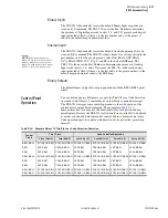
Table D.14
Example Object 12 Trip/Close or Code Selection Operation
Control
Points
Trip / Close
Code Selection Operation
Close (0x4X)
Trip (0x8X)
Latch On (3)
Latch Off (4)
Pulse On (1)
Pulse Off (2)
RB01:RB02
PULSE ON RB02 PULSE ON RB01 PULSE ON RB02 PULSE ON RB01 PULSE ON RB02 PULSE ON RB01
RB03
SET RB03
CLEAR RB03
SET RB03
CLEAR RB03
SET RB03
CLEAR RB03
RB04
SET RB04
CLEAR RB04
SET RB04
CLEAR RB04
SET RB04
CLEAR RB04
RB05:RB06
PULSE ON RB06 PULSE ON RB05 PULSE ON RB06 PULSE ON RB05 PULSE ON RB06 PULSE ON RB05
RB07
SET RB07
CLEAR RB07
SET RB07
CLEAR RB07
SET RB07
CLEAR RB07
RB08
SET RB08
CLEAR RB08
SET RB08
CLEAR RB08
SET RB08
CLEAR RB08
RB14:RB15
PULSE ON RB15 PULSE ON RB14 PULSE ON RB15 PULSE ON RB14 PULSE ON RB15 PULSE ON RB14
RB18:RB21
PULSE ON RB21 PULSE ON RB18 PULSE ON RB21 PULSE ON RB18 PULSE ON RB21 PULSE ON RB18
Summary of Contents for 751A
Page 1: ...20100129 SEL 751A Feeder Protection Relay Instruction Manual PM751A 01 NB...
Page 6: ...This page intentionally left blank...
Page 12: ...This page intentionally left blank...
Page 18: ...This page intentionally left blank...
Page 26: ...This page intentionally left blank...
Page 92: ...This page intentionally left blank...
Page 218: ...This page intentionally left blank...
Page 250: ...This page intentionally left blank...
Page 376: ...This page intentionally left blank...
Page 392: ...This page intentionally left blank...
Page 408: ...This page intentionally left blank...
Page 418: ...This page intentionally left blank...
Page 434: ...This page intentionally left blank...
Page 462: ...This page intentionally left blank...
Page 544: ...This page intentionally left blank...
Page 580: ...This page intentionally left blank...
Page 584: ...This page intentionally left blank...
Page 632: ...This page intentionally left blank...
Page 636: ...This page intentionally left blank...
Page 640: ...This page intentionally left blank...


