I.2
SEL-751A Relay
Instruction Manual
Date Code 20100129
M
IRRORED
B
ITS
Communications
Operation
Transmitting at longer intervals for baud rates above 9600 avoids overflowing
relays that receive M
IRRORED
B
ITS
at a slower rate.
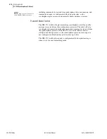
Message Reception
Overview
During synchronized M
IRRORED
B
ITS
communications with the
communications channel in normal state, the relay decodes and checks each
received message. If the message is valid, the relay sends each received logic
bit (RMB
n
, where
n
= 1 through 8) to the corresponding pickup and dropout
security counters, that in turn set or clear the RMB
n
A and RMB
n
B relay
element bits.
Message Decoding
and Integrity Checks
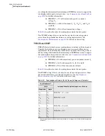
Set the RX_ID of the local SEL-751A to match the TX_ID of the remote
SEL-751A. The SEL-751A provides indication of the status of each
M
IRRORED
B
ITS
communications channel with Relay Word bits ROKA
(receive OK) and ROKB. During normal operation, the relay sets the ROK
c
(
c
= A or B). Upon detecting any of the following conditions, the relay clears
the ROK
c
bit when:
➤
The relay is disabled.
➤
M
IRRORED
B
ITS
are not enabled.
➤
Parity, framing, or overrun errors.
➤
Receive message identification error.
➤
No message received in the time three messages have been sent
when PROTO = MB
c
, or seven messages have been sent when
PROTO = MB8
c
.
➤
Loopback is enabled.
The relay asserts ROK
c
only after successful synchronization as described
below and two consecutive messages pass all of the data checks described
above. After ROK
c
is reasserted, received data may be delayed while passing
through the security counters described below.
While ROK
c
is deasserted, the relay does not transfer new RMB data to the
pickup-dropout security counters described below. Instead, the relay sends one
of the user-definable default values to the security counter inputs. For each
RMB
n
, use the RXDFLT setting to determine the default state the M
IRRORED
B
ITS
should use in place of received data if an error condition is detected. The
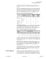
setting is a mask of 1s, 0s, and/or Xs (for RMB1A–RMB8A), where X
represents the most recently received valid value. The positions of the 1s and
0s correspond to the respective positions of the M
IRRORED
B
ITS
in the Relay
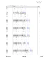
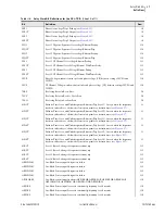
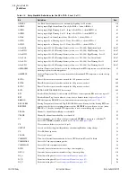
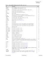
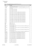
Word bits (see
).
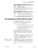
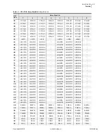
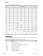
is an extract of
, showing the positions of the M
IRRORED
B
ITS
.
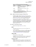
Table I.1
Number of M
IRRORED
B
ITS
Messages for Different Baud
Baud Rate
Transmission Rate of M
IRRORED
B
ITS
Packets
2400
15 ms
4800
7.5 ms
9600
4 times a power system cycle (automatic pacing mode)
19200
4 times a power system cycle (automatic pacing mode)
38400
4 times a power system cycle (automatic pacing mode)
Summary of Contents for 751A
Page 1: ...20100129 SEL 751A Feeder Protection Relay Instruction Manual PM751A 01 NB...
Page 6: ...This page intentionally left blank...
Page 12: ...This page intentionally left blank...
Page 18: ...This page intentionally left blank...
Page 26: ...This page intentionally left blank...
Page 92: ...This page intentionally left blank...
Page 218: ...This page intentionally left blank...
Page 250: ...This page intentionally left blank...
Page 376: ...This page intentionally left blank...
Page 392: ...This page intentionally left blank...
Page 408: ...This page intentionally left blank...
Page 418: ...This page intentionally left blank...
Page 434: ...This page intentionally left blank...
Page 462: ...This page intentionally left blank...
Page 544: ...This page intentionally left blank...
Page 580: ...This page intentionally left blank...
Page 584: ...This page intentionally left blank...
Page 632: ...This page intentionally left blank...
Page 636: ...This page intentionally left blank...
Page 640: ...This page intentionally left blank...


