4.100
SEL-751A Relay
Instruction Manual
Date Code 20100129
Protection and Logic Functions
Analog Inputs
Analog Inputs
The SEL-751A tracks the power system frequency and samples the analog
inputs four times per power system cycle. For analog inputs, set the following
parameters for each input:
➤
Analog type
➤
High and low input levels
➤
Engineering units
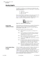
Because of the flexibility to install different cards in the rear-panel slots on the
device, the setting prompt adapts to the
x
and
y
variables shown in
. Variable
x
displays the slot position (
3
through
5
), and variable
y
displays the transducer (analog) input number (1 through 4 or 8).
Figure 4.55
Analog Input Card Adaptive Name
Analog Input
Calibration Process
In the analog input circuit, the dominant error is signal offset. To minimize the
signal offset, we adjust each of the device analog input channels by a
compensation factor. These compensation factors correct the signal offset
errors to within ±1 uA or ±1 mV.
Signal offset compensation factor calculation procedure:
Step 1. Turn the SEL-751A on and allow it to warm up for a few
minutes.
Step 2. Set the analog inputs for each analog channel to the desired
range using the AI
xxx
TYP, AI
xxx
L, AI
xxx
H, AI
xxx
EL, and
AI
xxx
EH settings (for example, ±1 mA).
Step 3. Short each analog input in turn at the device terminals using
short, low resistance leads with solid connections.
Step 4. Issue the command
MET AI 10
to obtain 10 measurements for
each channel.
Step 5. Record these 10 measurements, then calculate the average of
the 10 measurements by adding the 10 values algebraically, and
dividing the sum by 10. This is the average offset error in
engineering units at zero input (for example, –0.014 mA).
Step 6. Negate this value (flip the sign) and add the result to each of the
AI
xxx
EL and AI
xxx
EH quantities. For this example, the new
AI
xxx
EL and AI
xxx
EH values are –0.986 mA and 1.014 mA.
Analog Input Setting
Example
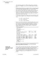
Assume we installed an analog card in Slot
3
. On Input 1 of this analog card,
we connect a 4–20 mA transducer driven from a device that measures
temperature on a transformer load tap changer mechanism. For this
temperature transducer, 4 mA corresponds to –50°C, and 20 mA corresponds
to 150°C. You have already installed the correct hardware jumper (see
for more information) for Input 1 to operate as a current input. At
power up, allow approximately five seconds for the SEL-751A to boot up,
perform self-diagnostics, and detect installed cards.
Inputs Number (1 through 8)
Slot Position (3 through 5)
Analog Input
AIx0y
Summary of Contents for 751A
Page 1: ...20100129 SEL 751A Feeder Protection Relay Instruction Manual PM751A 01 NB...
Page 6: ...This page intentionally left blank...
Page 12: ...This page intentionally left blank...
Page 18: ...This page intentionally left blank...
Page 26: ...This page intentionally left blank...
Page 92: ...This page intentionally left blank...
Page 218: ...This page intentionally left blank...
Page 250: ...This page intentionally left blank...
Page 376: ...This page intentionally left blank...
Page 392: ...This page intentionally left blank...
Page 408: ...This page intentionally left blank...
Page 418: ...This page intentionally left blank...
Page 434: ...This page intentionally left blank...
Page 462: ...This page intentionally left blank...
Page 544: ...This page intentionally left blank...
Page 580: ...This page intentionally left blank...
Page 584: ...This page intentionally left blank...
Page 632: ...This page intentionally left blank...
Page 636: ...This page intentionally left blank...
Page 640: ...This page intentionally left blank...


