background image

7.29

Date Code 20100129

Instruction Manual

SEL-751A Relay

Communications

SEL ASCII Protocol and Commands

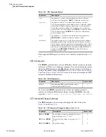
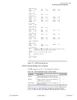
HELP Command

The 

HELP 

command (see 

Table 7.20

) gives a list of commands available at 

the present access level. You can also get a description of any particular 
command; type 

HELP 

followed by the name of the command for help on 

each command.

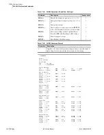
HISTORY Command

Use the 

HIS

 command (see 

Table 7.21

) to view a list of one-line descriptions 

of relay events or clear the list (and corresponding event reports) from 
nonvolatile memory.

For more information on event reports, see 

Section 9: Analyzing Events

.

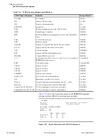
IDENTIFICATION Command

Use the 

ID

 command (see 

Table 7.22

) to extract device identification codes.

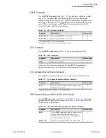
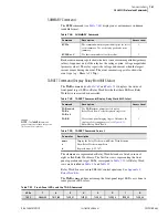
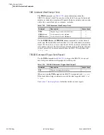
IRI Command

Use the 

IRI

 command to direct the relay to read the demodulated IRIG-B time 

code at the serial port or IRIG-B input (see 

Table 7.23

).

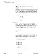
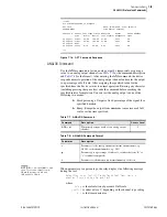
To force the relay to synchronize to IRIG-B, enter the following command:

=>

IRI <Enter>

Table 7.20

HELP Command

Command

Description

Access Level

HELP

Display a list of each command available at the 
present access level with a one-line description.

1

HELP


command

Display information on the command 

command

.

1

Table 7.21

HISTORY Command

Command

Description

Access Level

HIS

Return event histories with the oldest at the bottom 
of the list and the most recent at the top of the list.

1

HIS 

n

Return event histories with the oldest at the bottom 
of the list and the most recent at the top of the list, 
beginning at event 

n

.

1

HIS C or R

Clear/reset the event history and all corresponding 
event reports from nonvolatile memory.

1

Table 7.22

IDENTIFICATION Command

Command

Description

Access Level

ID

Return a list of device identification codes.

0

Table 7.23

IRI Command

Command

Description

Access Level

IRI

Force synchronization of internal control clock to 
IRIG-B time-code input.

1

Summary of Contents for 751A

Page 1: ...20100129 SEL 751A Feeder Protection Relay Instruction Manual PM751A 01 NB...

Page 2: ...uipment damage WARNING Seules des personnes qualifi es peuvent travailler sur cet appareil Si vous n tes pas qualifi s pour ce travail vous pourriez vous blesser avec d autres personnes ou endommager...

Page 3: ...ystem Installation 2 29 Field Serviceability 2 35 Section 3 PC Software Overview 3 1 Setup 3 2 Terminal 3 4 Settings Database Management and Drivers 3 5 Settings 3 6 Event Analysis 3 11 Meter and Cont...

Page 4: ...ction 6 Settings Overview 6 1 View Change Settings With Front Panel 6 2 View Change Settings Over Communications Port 6 4 Setting Entry Error Messages 6 5 SEL 751A Settings Sheets Section 7 Communicat...

Page 5: ...IEC 61850 Communications Features F 1 Introduction to IEC 61850 F 2 IEC 61850 Operation F 3 IEC 61850 Configuration F 10 Logical Node Extensions F 16 Logical Nodes F 18 Protocol Implementation Conform...

Page 6: ...This page intentionally left blank...

Page 7: ...current Settings 4 6 Table 4 6 Residual Overcurrent Settings 4 8 Table 4 7 Negative Sequence Overcurrent Settings 4 9 Table 4 8 Phase A B and C Time Overcurrent Settings 4 10 Table 4 9 Maximum Phase T...

Page 8: ...ble 4 61 Entries for the Four Strings 4 114 Table 4 62 Binary Entry in the Name String Only 4 116 Table 4 63 Analog Entry in the Name String Only 4 116 Table 4 64 Entry in the Name String and the Alia...

Page 9: ...UL OUTnnn Command 7 35 Table 7 36 QUIT Command 7 35 Table 7 37 R_S Command Restore Factory Defaults 7 35 Table 7 38 SER Command Sequential Events Recorder Report 7 35 Table 7 39 SER Command Format 7 3...

Page 10: ...tom DNP3 AI Map D 17 Table D 10 SEL 751A DNP3 Device Profile D 20 Table D 11 SEL 751A DNP Object List D 21 Table D 12 DNP3 Reference Data Map D 25 Table D 13 DNP3 Default Data Map D 26 Table D 14 Exam...

Page 11: ...onformance Statement F 28 Table F 22 VariableSpecification Conformance Statement F 29 Table F 23 Read Conformance Statement F 29 Table F 24 GetVariableAccessAttributes Conformance Statement F 29 Table...

Page 12: ...This page intentionally left blank...

Page 13: ...ase Voltage Connections 2 21 Figure 2 18 Voltage Connections 2 22 Figure 2 19 Typical Current Connections 2 23 Figure 2 20 SEL 751A Provides Overcurrent Protection and Reclosing for a Distribution Fee...

Page 14: ...Element Logic 4 31 Figure 4 19 Overvoltage Element Logic 4 32 Figure 4 20 Synchronism Check Voltage Window and Slip Frequency Elements 4 33 Figure 4 21 Synchronism Check Elements 4 34 Figure 4 22 Ang...

Page 15: ...for an Entry in a Boolean Name and Alias Strings and b Analog Name and User Text and Formatting Strings 4 117 Figure 4 71 Front Panel Display for an Entry in a Boolean Name and Alias Strings and b Ana...

Page 16: ...Command 7 40 Figure 8 1 Front Panel Overview 8 2 Figure 8 2 Access Level Security Padlock Symbol 8 3 Figure 8 3 Password Entry Screen 8 4 Figure 8 4 Front Panel Pushbuttons 8 4 Figure 8 5 Main Menu 8...

Page 17: ...ssor Configuration C 7 Figure D 1 Application Confirmation Timing With URETRY n 2 D 7 Figure D 2 Message Transmission Timing D 8 Figure D 3 Sample Response to SHO DNP Command D 14 Figure D 4 Port MAP...

Page 18: ...This page intentionally left blank...

Page 19: ...ection 6 Settings Describes how to enter and record settings for basic protection voltage based protection and RTD based protection Section 7 Communications Describes how to connect the SEL 751A to a...

Page 20: ...on and control elements Appendix K Analog Quantities Lists and describes the Analog Quantities outputs of analog elements SEL 751A Relay Command Summary Briefly describes the serial port commands that...

Page 21: ...nts formatted as follows Symbols The following symbols from EN 61010 1 are often marked on SEL products Indicates a potentially hazardous situation that if not avoided may result in minor or moderate...

Page 22: ...ce when facing the front of the device The following table shows LED information specific to the SEL 751A see Figure 2 10 for the location of the ports using these LEDs on the relay for low voltage su...

Page 23: ...ernet Port LEDs LED Safety Warnings and Precautions Do not look into the end of an optical cable connected to an optical output Do not look into the fiber ports connectors Do not perform any procedure...

Page 24: ...enclosure should be certified to these requirements or be tested for compliance as part of the complete assembly The figure shows the compliance label that is located on the left side of the device Pr...

Page 25: ...Avoid using abrasive materials polishing compounds and harsh chemical solvents such as xylene or acetone on any surface of the relay Technical Assistance Obtain technical assistance from the following...

Page 26: ...This page intentionally left blank...
Page 27: ...t test operate and maintain any SEL 751A You need not review the entire manual to perform specific tasks Features Standard Protection Features Phase Instantaneous Overcurrent 50P Ground Residual Insta...

Page 28: ...SEL 3010 Event Messenger A complete suite of accurate metering functions Communications and Control EIA 232 front panel port EIA 232 EIA 485 single or dual copper or fiber optic Ethernet and fiber opt...

Page 29: ...SEL MIRRORED BITS Event Messenger Synchrophasors with C37 118 Breaker Wear Monitoring Options Firmware option Autoreclosing Control Voltage Options see Table 1 1 Input Output I O Option Additional dig...

Page 30: ...eactive apparent power and power factor metering x x x x Energy metering x x x x Synchronism check ele ments including under and over voltage ele ments 25 27S 59S x x Station dc battery volt age monit...

Page 31: ...rams for various applications The following is a list of possible application scenarios Distribution feeder protection feeder protection with core balance CT Delta wye transformer overcurrent protecti...

Page 32: ...s two EIA 232 serial communications ports The following steps require PC terminal emulation software and an SEL Cable C234A or equivalent to connect the SEL 751A to the PC See Section 6 Settings for f...

Page 33: ...803 CID CD05 PART NUM 751A01B1X0X7386163X SELF TESTS W Warn FPGA GPSB HMI RAM ROM CR_RAM NON_VOL CLOCK CID_FILE 0 9V 1 2V OK OK OK OK OK OK OK OK OK 0 90 1 19 1 5V 1 8V 2 5V 3 3V 3 75V 5 0V 1 25V 5 0V...

Page 34: ...of each status report designator and Table 10 7 shows all the self tests performed by the relay The beginning of the status report printout see Figure 1 3 contains the relay serial number firmware ide...

Page 35: ...relay will reply with the stored time For example 13 52 44 This time is 1 52 p m and 44 seconds Changing the Time Enter TIM followed by the correct time at the action prompt to change the time stored...

Page 36: ...Range 19 2 52 8 Vdc Power Consumption 20 W dc Interruptions 10 ms 24 Vdc 50 ms 48 Vdc Output Contacts General OUT103 is Form C Trip Output all other outputs are Form A Dielectric Test Voltage 2000 Vac...

Page 37: ...ital Output Contact Temperature Derating for Operating at Elevated Temperatures Digital Output Cards Installed Operating Ambient Maximum Value of Current Ithe Duty Factor 1 3 less than or equal to 60...

Page 38: ...imum DeviceNet Communications Card Rating 60 C 140 F maximum Operating Environment Pollution Degree 2 Overvoltage Category II Atmospheric Pressure 80 110 kPa Relative Humidity 5 95 noncondensing Maxim...

Page 39: ...N elements in the 2 5 mA and 50 mA models have a built in 30 ms security qualifier time delay Accuracy 5 of setting 0 02 INOM A secondary Steady State pickup Time Delay 0 00 5 00 seconds 0 01 seconds...

Page 40: ...etection 50 C RTD Types PT100 NI100 NI120 CU10 RTD Lead Resistance 25 ohm max per lead Lead Length 10 m to meet IEC 60255 22 1 and IEC 60255 22 5 Update Rate 3 s Noise Immunity on RTD Inputs up to 1 4...

Page 41: ...ing guidelines for proper physical installation of the SEL 751A Physical Location You can mount the SEL 751A in a sheltered indoor environment a building or an enclosed cabinet that does not exceed th...

Page 42: ...six rear panel slots labeled as Slots A B C D E and Z Slots A B and Z are base unit slots each associated with a specific function Optional digital analog I O communications RTD and voltage cards are...

Page 43: ...s available on terminals B01 B02 for all models except models with fiber optic Ethernet port P1 and dual copper Ethernet port P1 that have Port 3 as an EIA 232 serial port and can input IRIG B via the...

Page 44: ...t 2 and Port 3 support the following protocols Modbus RTU Slave SEL ASCII and Compressed ASCII SEL Fast Meter SEL Fast Operate SEL Fast SER SEL Fast Message Unsolicited Write SEL Settings File Transfe...

Page 45: ...t Operate SEL Fast SER SEL Fast Message Unsolicited Write SEL Settings File Transfer SEL MIRRORED BITS MBA MBB MB8A MB8B MBTB MBTA Event Messenger DNP3 Slave Level 2 C37 118 Synchrophasor Data Voltage...

Page 46: ...Supported in Slot E only order this card when you have either single or three phase wye or delta PTs With a voltage card installed the SEL 751A tracks the frequency using positive sequence voltage and...

Page 47: ...0 25 A 5 A or 0 05 A 1 A Table 2 6 Current Card Terminal Designation Terminal Number Description 01 02 IA Phase A current input 03 04 IB Phase B current input 05 06 IC Phase C current input 07 08 IN...

Page 48: ...ware Reference Descriptiona a x 3 4 or 5 e g OUT401 OUT402 etc if the card was installed in Slot D 01 02 OUTx01 driven by OUTx01 SELOGIC equation 03 04 OUTx02 driven by OUTx02 SELOGIC equation 05 06 O...

Page 49: ...lled in Slot 4 Slot D the SELOGIC settings OUT401 404 would be available If OUT401 IN101 AND 51P1T and the card is moved to a different slot then the OUT4xx settings will be lost This is true for all...

Page 50: ...X Card Failure If you do not see this message and the ENABLED light is turned on the card was inserted into the wrong slot Begin again at Step 1 If you do see this message then proceed to Step 7 Step...

Page 51: ...analog output or a voltage analog output Figure 2 4 JMP1 Through JMP4 Locations on 4 AI 4 AO Board NOTE There is no jumper between pins 5 and 6 for a voltage analog output selection You need to insert...

Page 52: ...Output Jumpers Figure 2 6 Voltage Output Jumpers 9 5 1 10 6 2 JMP4 JMP4 Selected as Current Output 7 5 3 8 6 4 JMP1 JMP1 Selected as Voltage Output JMP1 A B C JMP1 A B C JMP1 A B C JMP1 A B C Passwor...

Page 53: ...SELBOOT you can only communicate with the relay via the front panel port To gain access to Level 1 and Level 2 command levels without passwords position the jumper in position A as shown in Figure 2 7...

Page 54: ...3 A I_04 08 05 06 02 04 09 03 1 0 1 1 1 2 1 3 1 4 1 5 1 6 07 0 1 A I_08 A I_06 A I_05 A I_07 AI_02 AI_0 1 AI_03 AI_04 08 05 06 02 04 09 03 1 0 1 1 1 2 1 3 1 4 1 5 1 6 07 0 1 5 Vdc RXD I RI G B TXD GND...

Page 55: ...of the connectors on the rear panel and side panel diagrams of three sample configurations of the SEL 751A are shown in Figure 2 9 Figure 2 10 and Figure 2 11 Figure 2 9 Fiber Optic Serial Ethernet E...

Page 56: ...Ethernet 8 DI RTD and 4 AI 4 AO Option Figure 2 11 Dual Fiber Optic Ethernet Fiber Optic Serial DeviceNet Fast Hybrid 4 DI 4 DO and Voltage Option With Monitoring Package i4159a i4162b A Rear Panel La...

Page 57: ...power disconnect circuit breaker or overcurrent device fuse must be 20 A An internal power supply fuse T 3 15 A H250 V 5 x 20 mm protects the operational power supply Be sure to use fuses that comply...

Page 58: ...cations processor via EIA 232 serial Port 3 may be used The available communications processors are the SEL 2032 SEL 2030 SEL 2020 and the SEL 2100 Logic Processor The models with fiber optic Ethernet...

Page 59: ...A04 OUT101 A05 A06 OUT102 A09 D03 COMP SHLD D02 D01 RTD01 D30 COMP SHLD D29 D28 RTD10 Up to Ten RTD Inputs Notes The chassis ground connector located on the rear panel card Slot A must always be conn...

Page 60: ...fail safe and nonfail safe trip modes setting selectable for all output contacts The following occurs in fail safe mode The relay coil is energized continuously if the SEL 751A is powered and operatio...

Page 61: ...se VT can be used Figure 2 17 and Figure 2 18 show the methods of connecting single phase and three phase voltages Figure 2 17 Single Phase Voltage Connections NOTE Current limiting fuses in direct co...

Page 62: ...ion Diagrams Figure 2 18 Voltage Connections A B C EO1 EO2 EO3 EO4 Direct Connection Wye Wye VT Connection Open Delta VT Connection SEL 751A A B C EO1 EO2 EO3 EO4 SEL 751A F1 F3 F1 F2 F3 EO5 EO6 VS NS...

Page 63: ...minals E07 VBAT and E08 VBAT of the SELECT 5AVI voltage card in slot E Refer to Section 5 Metering and Monitoring for details on the station dc battery monitor function and settings AC DC Connections...

Page 64: ...provides current IN for the neutral ground overcurrent elements Separate from Channel IN the residual ground overcurrent elements operate from the internally derived residual current IG IG 3I0 IA IB I...

Page 65: ...om Channel IN the residual ground overcurrent elements operate from the internally derived residual current IG IG 3I0 IA IB IC But in this residual connection example the neutral ground and residual g...

Page 66: ...minal See current input specifications in the subsection Specifications General on page 1 20 See neutral ground overcurrent element pickup specifications in Section 4 Protection and Logic Functions Fi...

Page 67: ...onal digital inputs and outputs Figure 2 23 SEL 751A Provides Overcurrent Protection for a Transformer Bank With a Tertiary Winding Wye Connected PTs TC Trip Coil 52A Trip Circuit IA C B A SEL 751A RE...

Page 68: ...rated at 2 5 mA nominal See current input specifications in the subsection Specifications General on page 1 20 See neutral ground overcurrent element pickup specifications in Section 4 Protection and...

Page 69: ...for arc flash protection Figure 2 25 SEL 751A With an Arc Flash Option Card and Fiber Optic Based Point Sensor Light Sensor Installation An arc flash system installation starts by selecting the best...

Page 70: ...gh easily detected by the sensor diagnostics such problems can be eliminated through careful installation planning Once routed fiber sensors are connected to the SEL 751A relay as shown in Figure 2 27...

Page 71: ...ntry point Figure 2 30 Figure 2 31 and Figure 2 32 show the sensor directivity pattern The point sensor must be located in clear view of energized parts which are most likely to cause an arc flash eve...

Page 72: ...Figure 2 32 Point Sensor Directivity Left to Right Above the Mounting Plane 120 100 80 60 40 20 0 0 350 10 340 20 330 30 320 40 310 50 300 60 290 70 280 80 270 90 260 100 250 110 240 120 230 130 220...

Page 73: ...er Sensor Mounting Example A bare fiber sensor consists of the major components shown in Figure 2 35 Two connector options V pin and ST are available for transitioning from the jacketed to the bare fi...

Page 74: ...n Example Figure 2 37 shows a typical switchgear application example with one incoming and two radial outgoing feeders All three feeders are protected with an SEL 751A relay controlling breakers 1 2 a...

Page 75: ...nd the real time clock battery A lithium battery powers the clock date and time if the external power source is lost or removed The battery is a 3 V lithium coin cell Ray O Vac BR2335 or equivalent At...

Page 76: ...ize the relay Step 2 Remove the four rear panel screws and the relay rear panel Step 3 Remove the Slot B printed circuit board Step 4 Locate the battery clip holder on the board Step 5 Carefully remov...

Page 77: ...ERATOR Architect SEL 5032 Software Configures IEC 61850 communications SEL 5040 ACSELERATOR Report Server SEL 5040 Software Automatically retrieves files and summarizes reports SEL 5601 ACSELERATOR An...

Page 78: ...kSet to communicate effectively with the relay Step 1 Select Communications from the ACSELERATOR QuickSet main menu bar as shown in Figure 3 1 Figure 3 1 Serial Port Communication Dialog Box Step 2 Se...

Page 79: ...3 3 Date Code 20100129 Instruction Manual SEL 751A Relay PC Software Setup Figure 3 2 Serial Port Communication Parameters Dialog Box Figure 3 3 Network Communication Parameters Dialog Box...

Page 80: ...rors in this file Click Communications Logging Connection Log to view the log Clear the log by selecting Communications Logging Clear Connection Log Drivers and Part Number After clicking Communicatio...

Page 81: ...relay or relay in the database in the Database Description and Settings Description dialog boxes Step 3 Enter special operating characteristics that describe the relay settings in the Settings Descri...

Page 82: ...re SEL 751A relays Store existing relay settings downloaded from SEL 751A relays with ACSELERATOR QuickSet creating a library of relay settings then modify and upload these settings from the settings...

Page 83: ...g box ACSELERATOR QuickSet uses the Z number in the FID string to create a particular version of settings To get started making SEL 751A settings with the Settings Editor in the Editor Mode select Fil...

Page 84: ...st match ACSELERATOR QuickSet uses this first portion of the Z number to determine the correct Settings Editor to display Figure 3 8 New Setting Screen File Open The Open menu item opens an existing d...

Page 85: ...ew to expand and select the settings you want to change Step 2 Use Tab to navigate through the settings or click on a setting Step 3 To restore the previous value for a setting right click the mouse o...

Page 86: ...Expression Builder displays all operands for that category in the list box at the bottom right side Directly underneath the right side of the equation choose operators to include in the RVALUE These...

Page 87: ...d analysis tools that help you retrieve information about relay operations quickly and easily Use the event information that the SEL 751A stores to evaluate the performance of a system select Tools Ev...

Page 88: ...1 Saving the Retrieved Event Enter a suitable name in the File name text box and select the appropriate location where ACSELERATOR QuickSet should save the event record View Event Files To view the sa...

Page 89: ...click on the text above the square you want to change After double clicking on the text a box with available Relay Word bits appears in the lower left corner of the screen Select the appropriate Relay...

Page 90: ...SER screens display the same information as the ASCII STA and SER commands Figure 3 13 shows the control screen From here you can reset metering data clear the Event History SER MIRRORED BITS report...

Page 91: ...Press F1 to open a context sensitive help file with the appropriate topic as the defaultf Table 3 4 Help Help Description General ACSELERATOR QuickSet Select Help from the main menu bar SEL 751A Sett...

Page 92: ...This page intentionally left blank...

Page 93: ...skip this subsection if your application does not include RTD inputs Voltage Based Protection Lists settings associated with undervoltage overvoltage power factor and synchronism check elements These...

Page 94: ...rce Describes setting used for choosing IRIG1 or IRIG2 as the time synchronization source Port Settings SET P Command Lists settings that configure the relay front and rear panel serial ports Front Pa...

Page 95: ...top of the responses to serial port commands to identify messages from individual relays Enter up to 16 characters including letters A Z not case sensitive numbers 0 9 periods dashes and spaces Sugge...

Page 96: ...to set DELTA_Y equal to WYE for an A N input or DELTA_Y equal to DELTA for an A B input voltage When you set SINGLEV equal to Y the relay performance changes in the following ways Voltage Elements Wh...

Page 97: ...esidual and negative sequence overcurrent as shown in Table 4 4 through Table 4 7 and in Figure 4 1 Each element can be torque controlled using appropriate SELOGIC control equations e g when 50P1TC IN...

Page 98: ...overcurrent element also operates on the output of a bipolar peak detector if the current waveform is highly distorted as is the case with severe CT saturation This ensures fast operation of the 50Pn...

Page 99: ...1P 50P1TC 50P1T 50PxP 50PxT 50NnP 50NnT Settings Maximum Phase Current Magnitude Core Balance Current Magnitude Residual Current Magnitude 50NnD 0 50PxD 0 Negative Sequence Current Calculation Negativ...

Page 100: ...2 Setting the Neutral OC CT Ratio CTRN see Figure 4 2 equal to 10 and Neutral Trip Lvl 50N1P equal to 0 5 A or lower with 0 10 second time delay ensures that the element will quickly detect and trip f...

Page 101: ...n a minimum response time RES OC TRIP DLY 0 00 5 00 sec 50G4D 0 50 RES OC TRQ CON SELOGIC 50G4TC 1 a For INOM 5 A b For INOM 1 A Table 4 7 Negative Sequence Overcurrent Settings Setting Prompt Setting...

Page 102: ...C5 51AC U3 TOC TIME DIAL 0 50 15 00c 0 05 1 00d c For 51_C U_ d For 51_C C_ 51ATD 3 00 EM RESET DELAY Y N 51ARS N CONST TIME ADDER 0 00 1 00 sec 51ACT 0 00 MIN RESPONSE TIM 0 00 1 00 51AMR 0 00 TOC TR...

Page 103: ...0 3 20 Ab 51P2P 6 00 51P2P 1 2 TOC CURVE SEL U1 U2 U3 U4 U5 C1 C2 C3 C4 C5 51P2C U3 TOC TIME DIAL 0 50 15 00c 0 05 1 00d 51P2TD 3 00 EM RESET DELAY Y N 51P2RS N CONST TIME ADDER 0 00 1 00 sec 51P2CT 0...

Page 104: ...2 U3 U4 U5 C1 C2 C3 C4 C5 51QC U3 TOC TIME DIAL 0 50 15 00c 0 05 1 00d c For 51_C U_ d For 51_C C_ 51QTD 3 00 EM RESET DELAY Y N 51QRS N CONST TIME ADDER 0 00 1 00 sec 51QCT 0 00 MIN RESPONSE TIM 0 00...

Page 105: ...DELAY Y N 51N1RS N CONST TIME ADDER 0 00 1 00 sec 51N1CT 0 00 MIN RESPONSE TIM 0 00 1 00 51N1MR 0 00 TOC TRQ CONTROL SELOGIC 51N1TC 1 TOC TRIP LVL OFF 0 50 16 00 Aa 0 10 3 20 Ab 0 13 2 00 mAc 5 0 160...

Page 106: ...51G1TD 1 50 EM RESET DELAY Y N 51G1RS N CONST TIME ADDER 0 00 1 00 sec 51G1CT 0 00 MIN RESPONSE TIM 0 00 1 00 51G1MR 0 00 TOC TRQ CONTROL SELOGIC 51G1TC 1 TOC TRIP LVL OFF 0 50 16 00 Aa 0 10 3 20 Ab 5...

Page 107: ...IN RESPONSE TIM 0 00 1 00 51G2MR 0 00 TOC TRQ CONTROL SELOGIC 51G2TC 1 a For INOM 5 A b For INOM 1 A c For 51_C U_ d For 51_C C_ Table 4 12 Residual Time Overcurrent Settings Sheet 2 of 2 Setting Prom...

Page 108: ...11 U5 Short Time Inverse Figure 4 12 Table 4 14 Equations Associated With IEC Curves Curve Type Operating Time Reset Time Figure C1 Standard Inverse Figure 4 13 C2 Very Inverse Figure 4 14 C3 Extreme...

Page 109: ...6 00 5 00 4 00 3 00 2 00 1 00 15 00 12 00 10 00 8 00 01 5 6 7 8 9 1 02 03 04 05 09 07 06 08 1 2 3 4 5 7 6 9 8 1 4 2 3 5 6 7 8 9 10 40 20 30 70 50 60 80 90 100 80 10 2 3 6 4 5 7 9 8 20 50 30 40 60 70...

Page 110: ...5 00 4 00 3 00 2 00 1 00 15 00 12 00 10 00 8 00 01 5 6 7 8 9 1 02 03 04 05 09 07 06 08 1 2 3 4 5 7 6 9 8 1 4 2 3 5 6 7 8 9 10 40 20 30 70 50 60 80 90 100 80 10 2 3 6 4 5 7 9 8 20 50 30 40 60 70 100 9...

Page 111: ...1 00 0 50 10 00 8 00 6 00 5 00 4 00 3 00 2 00 15 00 01 5 6 7 8 9 1 02 03 04 05 09 07 06 08 1 2 3 4 5 7 6 9 8 1 4 2 3 5 6 7 8 9 10 40 20 30 70 50 60 80 90 100 80 10 2 3 6 4 5 7 9 8 20 50 30 40 60 70 10...

Page 112: ...2 00 1 00 0 50 15 00 12 00 10 00 8 00 6 00 5 00 4 00 01 5 6 7 8 9 1 02 03 04 05 09 07 06 08 1 2 3 4 5 7 6 9 8 1 4 2 3 5 6 7 8 9 10 40 20 30 70 50 60 80 90 100 80 10 2 3 6 4 5 7 9 8 20 50 30 40 60 70...

Page 113: ...0 1 00 2 00 6 00 3 00 4 00 5 00 10 00 8 00 12 00 15 00 01 5 6 7 8 1 9 02 03 04 05 06 07 1 08 09 2 3 4 5 6 1 7 8 9 2 3 4 5 6 7 8 10 9 20 30 50 40 60 100 90 70 80 80 9 2 3 4 5 6 7 8 10 20 30 40 50 60 70...

Page 114: ...0 60 0 05 0 50 0 40 0 30 0 20 0 10 1 00 0 90 0 80 0 70 01 5 6 7 8 9 1 02 03 04 05 09 07 06 08 1 2 3 4 5 7 6 9 8 1 4 2 3 5 6 7 8 9 10 40 20 30 70 50 60 80 90 100 80 10 2 3 6 4 5 7 9 8 20 50 30 40 60 7...

Page 115: ...30 0 20 0 10 0 05 1 00 0 90 0 80 0 70 0 60 0 50 0 40 01 5 6 7 8 9 1 02 03 04 05 09 07 06 08 1 2 3 4 5 7 6 9 8 1 4 2 3 5 6 7 8 9 10 40 20 30 70 50 60 80 90 100 80 10 2 3 6 4 5 7 9 8 20 50 30 40 60 70...

Page 116: ...3 01 5 6 7 8 9 1 02 03 04 05 09 07 06 08 1 2 3 4 5 7 6 9 8 1 4 2 3 5 6 7 8 9 10 40 20 30 70 50 60 80 90 100 80 10 2 3 6 4 5 7 9 8 20 50 30 40 60 70 100 90 0 20 0 10 0 05 1 00 0 90 0 80 0 70 0 60 0 50...

Page 117: ...00 0 90 0 80 0 70 0 60 0 50 0 40 0 30 7 6 5 1 9 8 1 4 2 3 5 6 8 7 9 1 2 3 4 5 7 6 4 2 3 7 6 5 10 9 8 40 20 30 70 50 60 80 90 100 50 9 8 10 20 30 40 300 200 100 80 60 70 90 1000 900 800 700 600 500 40...

Page 118: ...20 30 40 50 60 70 80 90 100 1 2 3 4 5 6 7 8 9 1 2 3 4 5 6 7 8 9 01 02 03 04 05 06 07 08 09 100 1 2 3 4 5 6 7 8 9 5 6 7 8 9 90 80 70 60 50 40 30 20 10 Time in Seconds Time in Cycles 60 Hz 50 Hz 6000 5...

Page 119: ...uggestions If an RTD is not connected to an input or has failed in place and will not be replaced set the RTD location for that input equal to OFF For RTDs embedded in motor stator windings set the RT...

Page 120: ...tion is required if winding trip voting is not enabled Bearing trip voting works similarly The warning and trip temperature settings for bearing ambient and other RTD types function similarly except t...

Page 121: ...164 77 269 91 214 80 15 61 356 180 00 168 47 280 77 223 20 16 00 374 190 00 172 17 291 96 231 80 16 39 392 200 00 175 85 303 46 240 70 16 78 410 210 00 179 15 315 31 249 80 17 17 428 220 00 183 17 327...

Page 122: ...overvoltage elements These elements can be used to control reclosing logic described later Each of the elements has an associated time delay except the three phase under and overvoltage elements 3P27...

Page 123: ...tive Nominal Voltage When DELTA_Y WYE 27P1P Vnm VP max 27P1D 0 27P1T 27P2P Vnm 27P2D 0 27P2T Relay Word Bits 27P1 27P2 3P27 VP min When DELTA_Y DELTA 27P1P Vnm VPP max 27P1D 0 27P1T 27P2P Vnm 27P2D 0...

Page 124: ...ge Magnitude 3V2 Zero Sequence Voltage Magnitude 3V0 59S1P VS 59S1D 0 59S1T Synch Voltage Elements 59S2P 59S2D 0 59S2T Relay Word Bits 59S2 59S1 59S1P 59S2P 59P1P 59P2P 59Q1P 59Q2P 59G1P 59G2P Vnm Set...

Page 125: ...igure 4 21 The angle settings are checked for synchronism check closing If the voltages are not static voltages slipping with respect to one another the two synchronism check elements operate as shown...

Page 126: ...nce Angle Difference absolute value absolute value compensated by setting TCLOSD Synchronism Check Element 1 Synchronism Check Element 2 Synchronize at Angle Difference 0 Operation of Synchronism Chec...

Page 127: ...m checked with voltage VA VS does not lag VA The relay will display the setting entered SYNCPH VA or SYNCPH 0 The angle setting choices 0 30 300 or 330 degrees for setting SYNCPH are referenced to VA...

Page 128: ...ations may need a different setting For example Figure 2 20 requires 25RCF PTR 1 732 PTRS This will be 0 58 if the PTR and PTRS are equal See the Application Guide entitled Compensate for Constant Pha...

Page 129: ...ynchronism check logic outputs Relay Word bits SF 25A1 and 25A2 do not need to be used Block Synchronism Check Conditions Refer to Figure 4 20 The synchronism check element slip frequency calculator r...

Page 130: ...Figure 4 21 runs if the slip frequency is less than the maximum slip frequency setting 25SF Relay Word bit SF is asserted Voltages VP and VS Are Static Refer to top of Figure 4 21 If the slip frequen...

Page 131: ...e breaker close time into account with breaker close time setting TCLOSD set in ms see Figure 4 22 The Angle Difference Calculator calculates the Angle Difference between voltages VP and VS compensate...

Page 132: ...ifference increasing VS is moving away from VP Ideally circuit breaker closing is initiated when VS is in phase with VP Angle Difference 0 degrees Then when the circuit breaker main contacts finally c...

Page 133: ...Difference 0 degrees There might not be enough time to wait for this to happen Thus the Angle Difference 0 degrees restriction is eased for this scenario 3 Refer to Reclose Supervision Logic on page...

Page 134: ...c reclosing e g 79CLS 25A1 OR see Figure 4 31 Set 25ANG2 25 and use the resultant synchronism check element in manual close logic to supervise manual closing for example assert IN301 to initiate manua...

Page 135: ...Settings Setting Prompt Setting Range Setting Name Factory Default ENABLE PWR ELEM N 3P1 3P2 EPWR N 3PH PWR ELEM PU OFF 1 0 6500 0 VAa a The range shown is for 5 A input range for 1 A input is OFF 0 2...

Page 136: ...nt Relay Word bits SEL recommends a minimum time delay setting of 0 1 second for general applications The classical power calculation is a product of voltage and current to determine the real and reac...

Page 137: ...ip signal The power factor elements are enabled 55DLY seconds after Relay Word 52A is asserted breaker closed however when 55DLY 0 the element is always enabled irrespective of the 52A status Figure 4...

Page 138: ...tion Elements Undervoltage and directional power elements require accurate relaying potentials for correct operation It is critical that the relay detects an LOP condition and prevents operation of th...

Page 139: ...cycles Relay Word Bit I1 0 1 INOM I2 0 1 INOM I0 0 1 INOM 3 Table 4 22 Frequency Settings Setting Prompt Setting Range Setting Name Factory Default FREQ1 TRIP LEVEL OFF 20 00 70 00 Hz 81D1TP OFF FREQ1...

Page 140: ...he generated active power and restores the frequency to nominal value Failure of such control action may lead to system instability unless remedial action such as load shedding is taken You can use th...

Page 141: ...0 00 81R3 TRIP LEVEL OFF 0 10 15 00 81R3TP OFF 81R3 TREND INC DEC ABS 81R3TRND ABS 81R3 TRIP DELAY 0 10 60 00 sec 81R3TD 1 00 81R3 DO DELAY 0 00 60 00 sec 81R3DO 0 00 81R4 TRIP LEVEL OFF 0 10 15 00 8...

Page 142: ...is also supervised by Relay Word FREQTRK which ensures that the relay is tracking and measuring the system frequency Use the Relay Words 81RnT to operate output contacts to open appropriate breaker s...

Page 143: ...nd from front panel and serial ports are maintained for at least the duration of the minimum trip duration time TDURD setting TR Trip Conditions SELOGIC Control Equation The SEL 751A Trip Logic offers...

Page 144: ...ens and selected 50 51 elements are not picked up Minimum trip duration time TDURD passes The TR SELOGIC control equation result deasserts to logical 0 One of the following occurs Unlatch Trip SELOGIC...

Page 145: ...e an OR combination of all Relay Word bits that you want to cause the relay to close breaker The factory default setting already includes all commonly required Relay Word bits Unlatch Close Logic Once...

Page 146: ...tting 79CLSD is set 79CLSD 0 The above logic satisfies most applications Reclose Supervision Reclosing Relay Open Interval Timeout qualified by 79CLS Reclosing Relay Open Interval Timeout qualified by...

Page 147: ...ision Limit Time setting should be set to zero seconds 79CLSD 0 00 With this setting the logic in the top of Figure 4 31 is operative When an open interval times out the SELOGIC control equation reclo...

Page 148: ...is 79CLSD time window then the now qualified open interval time out will propagate onto the final close logic in Figure 4 30 to automatically reclose the circuit breaker If 79CLS remains deasserted to...

Page 149: ...ision condition 79CLS is not time limited When an open interval times out reclose supervision condition 79CLS is checked indefinitely until one of the other above unlatch conditions comes true The unl...

Page 150: ...timing after circuit breaker 52 1 at the remote end has reenergized the line The SEL 751A 2 has to see Bus 2 hot transmission line hot and in synchronism across open circuit breaker 52 2 for open int...

Page 151: ...a synchronism check reclose before timer 79CLSD times out or setting 79CLSD 0 00 and only one check is made If E79 3 which allows three automatic reclose attempts and the slipping voltages fail to co...

Page 152: ...Reset State The circuit breaker has been closed for a qualifying reset time The SEL 751A is ready to go through an automatic reclosing sequence in the reclose cycle state if the circuit breaker trips...

Page 153: ...o Lockout and Drive to Last Shot Settings 79DTL and 79DLS Respectively The Reclose Supervision Limit Timer setting 79CLSD times out see Figure 4 31 and top of Figure 4 32 and the reclose enable settin...

Page 154: ...terval 1 time setting 79OI1 0 00 then the reclosing relay is defeated and no automatic reclosing can occur If the reclosing relay is defeated the following also occur All three reclosing relay state R...

Page 155: ...2 79OI3 and 79OI4 are not operable In the factory settings both open interval times 79OI3 and 79OI4 are set to zero But if the settings were 79OI2 0 00 seconds 79OI3 15 00 seconds set to some value ot...

Page 156: ...Shot The number of reclosures is equal to the number of open interval time settings that precede the first open interval time setting set equal to zero The last shot value is also equal to the number...

Page 157: ...SLD settings are set independently setting 79RSLD can even be set greater than setting 79RSD if desired SELOGIC control equation setting 79BRS block reset timing can be set to control reset timing see...

Page 158: ...as to be at logical 1 79RIS logical 1 in order for open interval timing to be initiated If 79RIS logical 0 when setting 79RI senses a rising edge logical 0 to logical 1 transition the relay goes to th...

Page 159: ...initiate open interval timing With a long enough setting of the Minimum Trip Duration Timer TDURD the TRIP Relay Word bit will still be asserted to logical 1 when the circuit breaker opens see Figure...

Page 160: ...ple on page 4 68 Reclose initiation is by the breaker contact opening e g 79RI NOT 52A refer to Additional Settings Example on page 4 67 Then the drive to lockout condition overlaps reclose initiation...

Page 161: ...preceding discussion on settings 79RI and 79RIS the relay increments the shot counter to the next shot and then loads the open interval time corresponding to the new shot see Table 4 28 If the new sh...

Page 162: ...to shot 1 Then open interval 1 time setting 79OI1 is skipped and the relay times on the open interval 2 time setting 79OI2 instead In Table 4 29 note that the open interval 1 time setting 79OI1 is a...

Page 163: ...stall open interval timing conditions are desired make the following settings 79SKP 0 numeral 0 79STL 0 numeral 0 Block Reset Timing Setting 79BRS The block reset timing setting 79BRS keeps the reset...

Page 164: ...e trip reclose cycling EXAMPLE 4 17 Additional Settings Example 2 If the block reset timing setting is 79BRS 51P1P OR 51G1P then reset timing is blocked if time overcurrent pickup 51P1P or 51G1P is pi...

Page 165: ...mple 1 With sequence coordination setting 79SEQ 79RS AND 51P1P sequence coordination is operable only when the relay is in the Reset State 79RS logical 1 Refer to Figure 4 37 and Figure 4 38 Figure 4...

Page 166: ...s below the line recloser slow curve because the shot counter is now at shot 2 For this sequence coordination scheme the SELOGIC control equation trip equation is TR 51P1T AND SH0 OR SH1 OR 51AT OR 51...

Page 167: ...H0 logical 1 and then a permanent fault beyond the line recloser occurs fault current IF in Figure 4 37 the line recloser fast curve operates to clear the fault The SEL 751A also sees the fault The ph...

Page 168: ...The SEL 751A provides demand and peak demand metering selectable between thermal and rolling demand types for the following values IA IB IC phase currents A primary IG Residual ground current A primar...

Page 169: ...ng is momentarily suspended when SELOGIC control equation setting FAULT is asserted logical 1 The differences between thermal and rolling demand metering are explained in the following discussion Comp...

Page 170: ...ters to a Step Input Setting DMTC 15 minutes Thermal Demand Meter Response EDEM THM Thermal Demand Current per unit 0 0 5 10 15 0 5 0 9 1 0 Time Minutes Rolling Demand Meter Response EDEM ROL Rolling...

Page 171: ...or decreasing applied instantaneous current The thermal demand meter response time is based on the demand meter time constant setting DMTC see Table 4 30 Note in Figure 4 41 the thermal demand meter...

Page 172: ...emand meter response at Time 0 minutes 0 0 3 0 0 per unit Time 5 Minutes The three five minute intervals in the sliding time window at Time 5 minutes each integrate into the following five minute tota...

Page 173: ...h control switch also retains state even when power to the device is lost If the latch control switch is set to a programmable output contact and power to the device is lost the state of the latch con...

Page 174: ...deasserts to logical 0 You can use these latch bits in SELOGIC control equations to create custom logic for your application The SEL 751A includes 32 latches Table 4 32 shows the SET and RESET default...

Page 175: ...for all cumulative latch bit state changes Exceeding the limit can result in a flash self test failure An average of 70 cumulative latch bit state changes per day can be made for a 25 year device ser...

Page 176: ...imits it will be clipped at the limit value For example when the MV01 executed result is 16777219 00 MV01 will be 16777215 99 Similarly when the MV02 executed result is 16777238 00 MV02 will be 167772...

Page 177: ...1 with the following expression MV01 1 RB01 Now when Remote bit RB01 asserts Math variable MV01 has a value of 1 i e MV01 1 Boolean NOT Operator NOT Apply the NOT operator to a single Relay Word bit a...

Page 178: ...OT operator as long as the NOT operator precedes the R_TRIG operator The NOT R_TRIG combination produces a logical 0 for one processing interval when it detects a rising edge on the specified element...

Page 179: ...ot equal to a certain value an output contact is asserted OUT102 MV01 45 If the math variable MV01 is not equal to 45 in value output contact OUT102 asserts effectively OUT102 logical 1 If the math va...

Page 180: ...for more detail SV06PU SV06D0 SV07PU SV07D0 SV06 SV07 OUT101 OUT102 OUT103 OUT401 OUT101 OUT102 OUT401 Table 4 35 SELOGIC Variable Settings Setting Prompt Setting Range Default Settings SV TIMER PICK...

Page 181: ...the output SCnQU asserts follows SELOGIC setting SCnnCU Rising Edge Input Count Up increments the counter follows SELOGIC setting SCnnCD Rising Edge Input Count Down decrements the counter follows SEL...

Page 182: ...SC01CU has a rising edge a rising edge on SC01CD is ignored unless SC01 is already at the maximum value SC01PV 7 in which case SC01CU is ignored and the SC01CD is processed An example of this excepti...

Page 183: ...cted see Figure 2 16 the breaker is automatically tripped when relay control power fails MIRRORED BITS Transmit SELOGIC Control Equations See Appendix I MIRRORED BITS Communications and SEL 751A Setti...

Page 184: ...tering energy metering and demand metering Event Messenger Points The SEL 751A can be configured to automatically send ASCII message on a communications port when trigger condition is satisfied Use th...

Page 185: ...when triggered THE LOAD CURRENT IS 157 Location and resolution of the analog quantity value within the message can be specified by using pf where defines location of the value p defines number of digi...

Page 186: ...ay Word bit TRIP starts the BFD timer if the sum of positive sequence and negative sequence currents is above 0 02 INOM If the current remains above the threshold for BFD delay setting Relay Word bit...

Page 187: ...reases to 7 13 ms Fault clearing time will typically be longer determined by the breaker operating time which often adds three to five cycles This system supports two distinct types of fiber optic lig...

Page 188: ...ring enhanced security coupled with exceptionally fast operation Shape of the inverse time characteristic is fixed offering robust rejection of unrelated light events without adding unnecessary settin...

Page 189: ...element curve shape The element uses 32 samples per cycle data processed 16 times per cycle TOL element algorithm ensures that the light must be present for a minimum of two samples regardless of the...

Page 190: ...easily displayed by using the front panel METER Light Intensity menu as well as MET L command Set the pickup above the highest normal light intensity expected at each light sensor installation Arc fl...

Page 191: ...disabled set OUTxxxFS N To get additional speed select the fast hybrid output option card 4DI 4DO This card contains trip duty rated solid state output contacts which will operate within 50 s up to 8...

Page 192: ...sired range using the AIxxxTYP AIxxxL AIxxxH AIxxxEL and AIxxxEH settings for example 1 mA Step 3 Short each analog input in turn at the device terminals using short low resistance leads with solid co...

Page 193: ...ice at AI301TYP the next prompt enter V if this is a voltage driven device The next two settings define the lower level AI301L and the upper level AI301H of the transducer In this example the low leve...

Page 194: ...et inputs connected to voltage driven transducers in a similar way SET G AI301NAM TERSE Enter Global AI 301 Settings AI301 TAG NAME 8 characters AI301NAM AI301 TX_TEMP Enter AI301 TYPE I V AI301TYP I...

Page 195: ...rompt Setting Range Setting Name Factory Default AI301 TAG NAME 8 characters 0 9 A Z _ AI301NAM AI301 AI301 TYPE I V AI301TYP I AI301 LOW IN VAL 20 480 to 20 480 mA AI301L 4 000 AI301 HI IN VAL 20 480...

Page 196: ...Output Settings Station DC Battery Monitor The station dc battery monitor in the SEL 751A can alarm for under or overvoltage dc battery conditions and give a view of how much the station dc battery vo...

Page 197: ...s IN101R internal variable after analog to digital conversion On assertion IN101R starts Debounce Timer producing Relay Word bit IN101 after the debounce time delay The debounce timer is a pickup drop...

Page 198: ...1 deasserts to a logical 0 Table 4 49 shows the settings prompt setting range and factory default settings for a card in Slot C See the SEL 751A Settings Sheets for a complete list of input debounce s...

Page 199: ...ord bit DSABLSET asserts you can view the device settings from the front panel interface but you can only change settings using serial port commands Table 4 50 shows the settings prompt setting range...

Page 200: ...Factory Default IRIG TIME SOURCE IRIG1 IRIG2 TIME_SRC IRIG1 Table 4 52 Front Panel Serial Port Settings Setting Prompt Setting Range Setting Name Factory Default PROTOCOL SEL MOD EVMSG PMU PROTO SEL...

Page 201: ...t 2 1 65534 MODNUM2 502 Enable DNP Sessiona 0 3 EDNP 0 a See Table D 7 for a complete list of the DNP3 session settings Table 4 53 Ethernet Port Settings Sheet 2 of 2 Setting Prompt Setting Range Sett...

Page 202: ...TOP 1 PORT TIMEOUT 0 30 min T_OUT 5 SEND AUTOMESSAGE Y N AUTO N HDWR HANDSHAKING Y N RTSCTS N FAST OP MESSAGES Y N FASTOP N MODBUS SLAVE ID 1 247 SLAVEID 1 NOTE For additional settings when PROTO MBxx...

Page 203: ...ry Fast Operate messages at the serial port Set FASTOP N to block binary Fast Operate messages Refer to Appendix C SEL Communications Processors for the description of the SEL 751A Fast Operate comman...

Page 204: ...characters at a time you can enter up to 60 valid characters Valid characters are 0 9 A Z space For text exceeding 16 characters the LCD displays the first 16 characters then scrolls through the rema...

Page 205: ...ay to show TRFR 1 HV BRKR OPEN and when the HV circuit breaker is closed we want the display to show TRFR 1 HV BRKR CLOSED We also want similar displays for the LV breaker After connecting a form a no...

Page 206: ...4 63 shows the display when both HV and LV breakers are open both IN101 and IN102 deasserted Figure 4 64 shows the display when the HV breaker is closed and the LV breaker is open IN101 asserted but...

Page 207: ...IN101 now deasserts the relay still displays the line with the HV breaker information but the state is left blank as shown in Figure 4 67 Figure 4 67 Front Panel Display HV Breaker Open LV Breaker Cl...

Page 208: ...nter DP02 TID 16 AI301 TEMPERATURE Enter where Name Analog quantity name AI301 for example All analog quantities occupy two lines on the front panel display all binary quantities occupy one line on th...

Page 209: ...he fixed text as the alias text For example to display the word DEFAULT and SETTINGS on two different lines use a display point for each word i e DP01 1 DEFAULT and DP02 1 SETTINGS The following table...

Page 210: ...SPLAY POINT DP02 60 characters DP02 IN102 TRFR 1 LV BRKR CLOSED OPEN Enter DISPLAY POINT DP03 60 characters DP03 IAV IAV CURR 5 A AI301 HOT SPOT TEMP Enter DISPLAY POINT DP04 60 characters DP04 IG_MAG...

Page 211: ...pears on the display when LBnn deasserts OPEN for example SLBnn Set local bit Enter the text that describes the intended operation of the switch this text appears on the display when LBnn asserts CLOS...

Page 212: ..._ LABEL 7 characters Enter NA to null CLB02 OFF Enter SET LB_ LABEL 7 characters Enter NA to null SLB02 NA Enter PULSE LB_ LABEL 7 characters Enter NA to null PLB02 START Enter Save changes Y N Y Ente...

Page 213: ...Y N T01LEDL Y LED1 EQUATION SELOGIC T01_LED ORED50T TRIP LATCH T_LED Y N T02LEDL Y LED2 EQUATION SELOGIC T02_LED 51AT OR 51BT OR 51CT OR 51P1T OR 51P2T TRIP LATCH T_LED Y N T03LEDL Y LED3 EQUATION SEL...

Page 214: ...SRDLTIM SER Delete Time that mask the chattering SER element Setting SRDLTIM declares a time interval during which the relay qualifies an input by comparing the changes of state of each input against...

Page 215: ...ttings by entering the Relay Word bit name a space the desired alias a space the text to display when the condition asserts a space and the text to display when the condition deasserts ALIAS1 PB01 FP_...

Page 216: ...n 1 2 or 3 Table 4 74 shows the available settings See Appendix D DNP3 Communications for additional details Table 4 72 Event Report Settings Setting Prompt Setting Range Setting Name Factory Default...

Page 217: ...Name 24 characters AI_99 NA DNP Analog Output Label Name 6 characters AO_00 NA DNP Analog Output Label Name 6 characters AO_31 NA DNP Counter Label Name 11 characters CO_00 NA DNP Counter Label Name...

Page 218: ...This page intentionally left blank...
Page 219: ...bus TCP via Ethernet port DNP3 Serial via EIA 232 port or EIA 485 port DNP3 LAN WAN via Ethernet port DeviceNet port Analog outputs IEC 61850 via Ethernet port C37 118 Synchrophasor Protocol via seria...

Page 220: ...er data fall into the following categories Fundamental metering Thermal metering RTD metering with the external SEL 2600 RTD Module or an internal RTD option Energy metering Maximum and minimum meteri...

Page 221: ...Option Meter Values All Models Line Currents IA IB IC and IN Core Balance Ground Fault Current magnitudes A and phase angles deg IG Residual Ground Fault Current magnitude A and phase angle deg IAV A...

Page 222: ...G VS Volt Mag V pri 22222 6 22229 8 22237 5 322 9 22002 8 Volt Angle deg 0 0 119 4 121 0 112 9 1 3 Avg Phase V pri 22230 Neg Seq Volt 3V2 V pri 326 1 Voltage Imb 0 0 A B C 3P Real Pwr kW 44886 44660 4...

Page 223: ...energy out of bus into feeder MWh3P IN Real 3 phase energy from feeder into bus MVARh3P OUT Reactive 3 phase energy out of bus into feeder MVARh3P IN Reactive 3 phase energy from feeder into bus MVAh...

Page 224: ...ed if relay element FAULT is deasserted no fault condition exists for at least one second Additionally the following minimum thresholds must also be met Current values IA IB IC and IN 3 of the nominal...

Page 225: ...08 03 54 34 Figure 5 6 Device Response to the METER M Command To reset maximum minimum meter values issue the METER RM command as shown in Figure 5 7 The max min meter values can be reset from the ser...

Page 226: ...urrent transducers These values can then be used for automation and control applications within an industrial plant or application Through the global settings you can set each type of analog input to...

Page 227: ...tering or EDEM ROL Rolling Demand Metering The relay provides demand METER DE command and peak demand METER PE command metering Table 5 6 shows the values reported Figure 5 12 provides an example of t...

Page 228: ...corresponding port must have the AUTO setting set to YES Y The METER PM command will only operate when the SEL 751A is in the IRIG timekeeping mode as indicated by Relay Word bit TSOK logical 1 Table...

Page 229: ...33 5914 892 0 889 14 02 21 2007 12 01 23 923 277 630 13821 01 5907 527 0 889 13 02 21 2007 12 06 24 010 278 048 13821 97 5917 934 0 889 12 02 21 2007 12 11 24 140 277 988 13824 35 5917 830 0 889 11 0...

Page 230: ...rvoltage Elements Logic outputs DCLO and DCHI in Figure 5 15 operate as follows Create Desired Logic for DC Under and Overvoltage Alarming Pickup settings DCLOP and DCHIP are set independently Thus th...

Page 231: ...tacts deassert on total loss of power Thus the resultant dc voltage element at the bottom of Figure 5 16 would probably be a better choice see following discussion DCLO DCHI Bottom of Figure 5 16 Outp...

Page 232: ...anel The information available via the previously discussed METER serial port command is also available via the front panel Meter Menu See Figure 8 6 Analyze Station DC Battery Voltage The station dc...

Page 233: ...the SELOGIC control equation event report generation setting ER F_TRIG SVnT OR Timer output SVnT is an example dc voltage element from the bottom of Figure 5 16 Anytime dc voltage falls below pickup...

Page 234: ...nt interruption level Set Point 2 COSP2 number of close open operations that correspond to some midpoint current interruption level Set Point 3 COSP3 number of close open operations that correspond to...

Page 235: ...5 9 and Figure 5 17 Figure 5 18 shows the resultant breaker maintenance curve COSP1 10000 COSP2 150 COSP3 12 KASP1 1 20 KASP2 8 00 KASP3 20 00 Figure 5 17 Plotted Breaker Maintenance Points for a 25 k...

Page 236: ...enance information in Table 5 9 and Figure 5 17 but it does not have to be Set point KASP2 COSP2 should be set to provide the best curve fit with the plotted breaker maintenance points in Figure 5 17...

Page 237: ...efault settings the SELOGIC control equation breaker monitor initiation setting is set BKMON TRIP TRIP is the logic output of Figure 4 29 Refer to Figure 5 19 When BKMON asserts Relay Word bit TRIP go...

Page 238: ...current levels 0 Percent to 10 Percent Breaker Wear Refer to Figure 5 20 7 0 kA is interrupted 20 times 20 close open operations 20 0 pushing the breaker maintenance curve from the 0 percent wear lev...

Page 239: ...aker maintenance curve from the 10 percent wear level to the 25 percent wear level Compare the 100 percent and 25 percent curves and note that for a given current value the 25 percent curve has only 1...

Page 240: ...ker maintenance curve from the 25 percent wear level to the 50 percent wear level Compare the 100 percent and 50 percent curves and note that for a given current value the 50 percent curve has only 1...

Page 241: ...cent for a particular phase the percentage wear remains at 100 percent even if additional current is interrupted until reset by the BRE R command see View or Reset Breaker Monitor Information on page...

Page 242: ...terrupted current from externally initiated trips Percent circuit breaker contact wear for each phase Date when the preceding items were last reset via the BRE R command See Section 7 Communications T...

Page 243: ...d under relay initiated trips Rly Trips If TRIP is deasserted TRIP logical 0 the current and trip count information is accumulated under externally initiated trips Ext Trips Regardless of whether the...

Page 244: ...is because when BKMON is newly asserted input INxxx energized the TRIP Relay Word bit is asserted Thus the current and trip count information is accumulated under relay initiated trips Rly Trips If th...

Page 245: ...ettings entry The SEL 751A Settings Sheets at the end of this section list all SEL 751A settings the setting definitions and input ranges Refer to Section 4 Protection and Logic Functions for detailed...

Page 246: ...the RELAY settings as listed in the SEL 751A Settings Sheets Use the Up Arrow Down Arrow Left Arrow and Right Arrow pushbuttons to scroll through the relay settings View and change the settings accor...

Page 247: ...to return to the previous list Press to select an underlined menu item PTR Setting PHASE PT RATIO PTR 00120 00 Config Menu CTR 100 CTRN 100 PTR 120 00 SINGLEV N GROUP 1 2 3 Set Show Menu Global Group...

Page 248: ...nd Description SHOW n Show relay group settings n specifies the settings group 1 2 or 3 n defaults to active settings group if not listed SHO L n Show logic settings n specifies the settings group 1 2...

Page 249: ...eenter the setting In addition to the immediate range check several of the settings have interdependency checks with other settings The relay checks setting interdependencies after you answer Y to the...

Page 250: ...This page intentionally left blank...

Page 251: ...6 5 The settings are not case sensitive Group Settings SET Command Identifier UNIT ID LINE 1 16 Characters RID UNIT ID LINE 2 16 Characters TID Configuration PHASE CT RATIO 1 5000 CTR NEUTRAL CT RATI...

Page 252: ...1 A nom 0 13 12 50 mA 2 5 mA nom 5 0 1000 0 mA 50 mA nom 50N2P NEUT OC TRIP DLY 0 00 5 00 sec Hidden if 50N2P OFF 50N2D NEUT OC TRQ CON SELOGIC Hidden if 50N2P OFF 50N2TC NEUT OC TRIP LVL OFF 0 50 10...

Page 253: ...SEQ OC TRIP DLY 0 1 120 0 sec Hidden if 50Q2P OFF 50Q2D NSEQ OC TRQ CON SELOGIC Hidden if 50Q2P OFF 50Q2TC NSEQ OC TRIP LVL OFF 0 50 100 00 A 5 A nom 0 10 20 00 A 1 A nom 50Q3P NSEQ OC TRIP DLY 0 1 12...

Page 254: ...RS CONST TIME ADDER 0 00 1 00 sec Hidden if 51CP OFF 51CCT MIN RESPONSE TIM 0 00 1 00 sec Hidden if 51CP OFF 51CMR TOC TRQ CONTROL SELOGIC Hidden if 51CP OFF 51CTC Maximum Phase Time Overcurrent TOC T...

Page 255: ...F 0 50 16 00 A 5 A nom 0 10 3 20 A 1 A nom 0 13 2 00 mA 2 5 mA nom 5 0 160 0 mA 50 mA nom 51N1P TOC CURVE SEL U1 U2 U3 U4 U5 C1 C2 C3 C4 C5 Hidden if 51N1P OFF 51N1C TOC TIME DIAL 0 50 15 00 if 51_C U...

Page 256: ...4 C5 Hidden if 51G2P OFF 51G2C TOC TIME DIAL 0 50 15 00 if 51_C U_ 0 05 1 00 if 51_C C_ Hidden if 51G2P OFF 51G2TD EM RESET DELAY Y N Hidden if 51G2P OFF 51G2RS CONST TIME ADDER 0 00 1 00 sec Hidden i...

Page 257: ...idden if RTD5LOC OFF RTD5TY RTD5 TRIP LEVEL OFF 1 250 degC Hidden if RTD5LOC OFF TRTMP5 RTD5 WARN LEVEL OFF 1 250 degC Hidden if RTD5LOC OFF ALTMP5 RTD6 LOCATION OFF WDG BRG AMB OTH RTD6LOC RTD6 TYPE...

Page 258: ...TD11LOC OFF or E49RTD INT TRTMP11 RTD11 WARN LEVEL OFF 1 250 degC Hidden if RTD11LOC OFF or E49RTD INT ALTMP11 RTD12 LOCATION OFF WDG BRG AMB OTH Hidden if E49RTD INT RTD12LOC RTD12 TYPE PT100 NI100 N...

Page 259: ...ZS OV TRIP2 DLY 0 0 120 0 sec Hidden if 59G2P OFF 59G2D NSQ OV TRIP1 LVL OFF 0 02 1 20 xVnm 59Q1P NSQ OV TRIP1 DLY 0 0 120 0 sec Hidden if 59Q1P OFF 59Q1D NSQ OV TRIP2 LVL OFF 0 02 1 20 xVnm 59Q2P NSQ...

Page 260: ...LEVEL OFF 0 05 0 99 55LDAP PF WARN DELAY 1 240 sec Hidden if both 55LDAP and 55LGAP OFF 55AD PF ARMING DELAY 0 5000 sec Hidden if all 55LGTP 55LDTP 55LGAP and 55LDAP OFF 55DLY Frequency FREQ1 TRIP LE...

Page 261: ...81R2TRND 81R2 TRIP DELAY 0 10 60 00 sec Hidden if 81R2TP OFF 81R2TD 81R2 DO DELAY 0 00 60 00 sec Hidden if 81R2TP OFF 81R2DO 81R3 TRIP LEVEL OFF 0 10 15 00 Hz sec 81R3TP 81R3 TREND INC DEC ABS Hidden...

Page 262: ...ARS VARS Hidden if 3PRW2P OFF or if EPWR 3P1 PWR2T PWR ELEM DELAY 0 0 240 0 s Hidden if 3PRW2P OFF or if EPWR 3P1 PWR2D Trip Close Logic MIN TRIP TIME 0 0 400 0 sec TDURD CLOSE FAIL DLY 0 0 400 0 sec...

Page 263: ...S SKIP SHOT SELOGIC 79SKP STALL OPN INTRVL SELOGIC 79STL BLOCK RESET TMNG SELOGIC 79BRS SEQ COORDINATION SELOGIC 79SEQ RCLS SUPERVISION SELOGIC 79CLS Logic Settings SET L Command SELOGIC Enables SELOG...

Page 264: ...struction Manual Date Code 20100129 Date________________ RST10 SET11 RST11 SET12 RST12 SET13 RST13 SET14 RST14 SET15 RST15 SET16 RST16 SET17 RST17 SET18 RST18 SET19 RST19 SET20 RST20 SET21 RST21 SET22...

Page 265: ...ROPOUT 0 00 3000 00 sec SV03DO SV INPUT SELOGIC SV03 SV TIMER PICKUP 0 00 3000 00 sec SV04PU SV TIMER DROPOUT 0 00 3000 00 sec SV04DO SV INPUT SELOGIC SV04 SV TIMER PICKUP 0 00 3000 00 sec SV05PU SV T...

Page 266: ...13DO SV INPUT SELOGIC SV13 SV TIMER PICKUP 0 00 3000 00 sec SV14PU SV TIMER DROPOUT 0 00 3000 00 sec SV14DO SV INPUT SELOGIC SV14 SV TIMER PICKUP 0 00 3000 00 sec SV15PU SV TIMER DROPOUT 0 00 3000 00...

Page 267: ...TIMER PICKUP 0 00 3000 00 sec SV25PU SV TIMER DROPOUT 0 00 3000 00 sec SV25DO SV INPUT SELOGIC SV25 SV TIMER PICKUP 0 00 3000 00 sec SV26PU SV TIMER DROPOUT 0 00 3000 00 sec SV26DO SV INPUT SELOGIC SV...

Page 268: ...NT UP INPUT SELOGIC SC02CU SC CNT DN INPUT SELOGIC SC02CD SC PRESET VALUE 1 65000 SC03PV SC RESET INPUT SELOGIC SC03R SC LOAD PV INPUT SELOGIC SC03LD SC CNT UP INPUT SELOGIC SC03CU SC CNT DN INPUT SEL...

Page 269: ...SELOGIC SC09R SC LOAD PV INPUT SELOGIC SC09LD SC CNT UP INPUT SELOGIC SC09CU SC CNT DN INPUT SELOGIC SC09CD SC PRESET VALUE 1 65000 SC10PV SC RESET INPUT SELOGIC SC10R SC LOAD PV INPUT SELOGIC SC10LD...

Page 270: ...E 1 65000 SC16PV SC RESET INPUT SELOGIC SC16R SC LOAD PV INPUT SELOGIC SC16LD SC CNT UP INPUT SELOGIC SC16CU SC CNT DN INPUT SELOGIC SC16CD SC PRESET VALUE 1 65000 SC17PV SC RESET INPUT SELOGIC SC17R...

Page 271: ...UT SELOGIC SC22CD SC PRESET VALUE 1 65000 SC23PV SC RESET INPUT SELOGIC SC23R SC LOAD PV INPUT SELOGIC SC23LD SC CNT UP INPUT SELOGIC SC23CU SC CNT DN INPUT SELOGIC SC23CD SC PRESET VALUE 1 65000 SC24...

Page 272: ...RESET INPUT SELOGIC SC29R SC LOAD PV INPUT SELOGIC SC29LD SC CNT UP INPUT SELOGIC SC29CU SC CNT DN INPUT SELOGIC SC29CD SC PRESET VALUE 1 65000 SC30PV SC RESET INPUT SELOGIC SC30R SC LOAD PV INPUT SE...

Page 273: ...tings Sheets Logic Settings SET L Command MV06 MV07 MV08 MV09 MV10 MV11 MV12 MV13 MV14 MV15 MV16 MV17 MV18 MV19 MV20 MV21 MV22 MV23 MV24 MV25 MV26 MV27 MV28 MV29 MV30 MV31 MV32 Base Output OUT101 FAIL...

Page 274: ...FS OUT304 Slot D Output Hidden If Output Option Not Included OUT401 FAIL SAFE Y N OUT401FS OUT401 OUT402 FAIL SAFE Y N OUT402FS OUT402 OUT403 FAIL SAFE Y N OUT403FS OUT403 OUT404 FAIL SAFE Y N OUT404F...

Page 275: ...EMP are visible MESSENGER POINT MP01 TRIGGER Off 1 Relay Word bit MPTR01 MESSENGER POINT MP01 AQ None 1 analog quantity MPAQ01 MESSENGER POINT MP01 TEXT 148 characters MPTX01 MESSENGER POINT MP02 TRIG...

Page 276: ...uantity MPAQ09 MESSENGER POINT MP09 TEXT 148 characters MPTX09 MESSENGER POINT MP10 TRIGGER Off 1 Relay Word bit MPTR10 MESSENGER POINT MP10 AQ None 1 analog quantity MPAQ10 MESSENGER POINT MP10 TEXT...

Page 277: ...MPTX20 MESSENGER POINT MP21 TRIGGER Off 1 Relay Word bit MPTR21 MESSENGER POINT MP21 AQ None 1 analog quantity MPAQ21 MESSENGER POINT MP21 TEXT 148 characters MPTX21 MESSENGER POINT MP22 TRIGGER Off...

Page 278: ...31 TRIGGER Off 1 Relay Word bit MPTR31 MESSENGER POINT MP31 AQ None 1 analog quantity MPAQ31 MESSENGER POINT MP31 TEXT 148 characters MPTX31 MESSENGER POINT MP32 TRIGGER Off 1 Relay Word bit MPTR32 ME...

Page 279: ...phase 50PAFP Note All settings below are Hidden if 50PAFP OFF AF N OC TRP LVL OFF 0 50 100 00 A 5 A nom neutral 0 10 20 00 A 1 A nom neutral 50NAFP SENSOR 1 TYPE NONE POINT FIBER AFSENS1 TOL 1 PICKUP...

Page 280: ...000 AIx01LAL AIx01 HI WARN L1 OFF 99999 000 to 99999 000 AIx01HW1 AIx01 HI WARN L2 OFF 99999 000 to 99999 000 AIx01HW2 AIx01 HI ALARM OFF 99999 000 to 99999 000 AIx01HAL AIx02 AIx02 TAG NAME 8 charact...

Page 281: ...ARM OFF 99999 000 to 99999 000 AIx03LAL AIx03 HI WARN L1 OFF 99999 000 to 99999 000 AIx03HW1 AIx03 HI WARN L2 OFF 99999 000 to 99999 000 AIx03HW2 AIx03 HI ALARM OFF 99999 000 to 99999 000 AIx03HAL AIx...

Page 282: ...000 AIx05LW1 AIx05 LO WARN L2 OFF 99999 000 to 99999 000 AIx05LW2 AIx05 LO ALARM OFF 99999 000 to 99999 000 AIx05LAL AIx05 HI WARN L1 OFF 99999 000 to 99999 000 AIx05HW1 AIx05 HI WARN L2 OFF 99999 00...

Page 283: ...0 to 99999 000 AIx07EL AIx07 EU HI 99999 000 to 99999 000 AIx07EH AIx07 LO WARN L1 OFF 99999 000 to 99999 000 AIx07LW1 AIx07 LO WARN L2 OFF 99999 000 to 99999 000 AIx07LW2 AIx07 LO ALARM OFF 99999 000...

Page 284: ...x01 LO OUT VAL 20 480 to 20 480 mA AOx01L AOx01 HI OUT VAL 20 480 to 20 480 mA AOx01H If AOx01TYP V AOx01 LO OUT VAL 10 240 to 10 240 V AOx01L AOx01 HI OUT VAL 10 240 to 10 240 V AOx01H AOx02 AOx02 AN...

Page 285: ...A AOx04H If AOx04TYP V AOx04 LO OUT VAL 10 240 to 10 240 V AOx04L AOx04 HI OUT VAL 10 240 to 10 240 V AOx04H Station DC Battery Monitor Hidden if Voltage Option xx73xx or xx74xx not included see Table...

Page 286: ...en If Input Option Not Included IN501 Debounce AC 0 65000 ms IN501D IN502 Debounce AC 0 65000 ms IN502D IN503 Debounce AC 0 65000 ms IN503D IN504 Debounce AC 0 65000 ms IN504D IN505 Debounce AC 0 6500...

Page 287: ...0 9600 19200 38400 bps SPEED DATA BITS 7 8 bits Hidden if PROTO MOD EVMSG or PMU BITS PARITY O E N Hidden if PROTO EVMSG or PMU PARITY STOP BITS 1 2 bits Hidden if PROTO MOD or EVMSG STOP PORT TIME OU...

Page 288: ...0 Mbps Hidden if not dual redundant Ethernet Port option NETBSPD TELNET PORT 23 1025 65534 TPORT TELNET TIME OUT 1 30 min TIDLE FTP USER NAME 20 characters FTPUSER Enable IEC 61850 Protocol Y N Hidden...

Page 289: ...767 TIMERQ1 Seconds to Select Operate Time Out 0 0 30 0 STIMEO1 Seconds to send Data Link Heartbeat 0 7200 Hidden if DNPTR1 UDP DNPINA1 Event Message Confirm Time Out 1 50 sec ETIMEO1 Enable Unsolicit...

Page 290: ...Out 0 0 30 0 STIMEO2 Seconds to send Data Link Heartbeat 0 7200 Hidden if DNPTR2 UDP DNPINA2 Event Message Confirm Time Out 1 50 sec ETIMEO2 Enable Unsolicited Reporting Y N Hidden if ECLASSA2 0 ECLA...

Page 291: ...Hidden if DNPTR3 UDP DNPINA3 Event Message Confirm Time Out 1 50 sec ETIMEO3 Enable Unsolicited Reporting Y N Hidden if ECLASSA3 0 ECLASSB3 0 ECLASSC3 0 and ECLASSV3 0 UNSOL3 Enable Unsolicited Report...

Page 292: ...ss for Binary Event Data 0 3 ECLASSB1 Class for Counter Event Data 0 3 ECLASSC1 Class for Analog Event Data 0 3 ECLASSA1 Currents Scaling Decimal Places 0 3 DECPLA1 Voltages Scaling Decimal Places 0 3...

Page 293: ...00 CBADPU MB Receive Default State 8 characters RXDFLT RMB1 Pickup Debounce Messages 1 8 RMB1PU RMB1 Dropout Debounce Messages 1 8 RMB1DO RMB2 Pickup Debounce Messages 1 8 RMB2PU RMB2 Dropout Debounce...

Page 294: ...G or MB_ FASTOP Modbus MODBUS SLAVE ID 1 247 Hidden if PROTO SEL EVMSG or MB_ SLAVEID DNP3 Protocol Hidden if PROTO SEL EVMSG MB PMU or MOD DNP Address 0 65519 DNPADR DNP Address to Report to 0 65519...

Page 295: ...N UTIMEO1 Minimum Seconds from DCD to TX 0 00 1 00 MINDLY Maximum Seconds from DCD to TX 0 00 1 00 MAXDLY Settle Time from RTS On to TX OFF 0 00 30 00 sec PREDLY Settle Time from TX to RTS OFF 0 00 30...

Page 296: ...8 RMB7PU RMB7 Dropout Debounce Messages 1 8 RMB7DO RMB8 Pickup Debounce Messages 1 8 RMB8PU RMB8 Dropout Debounce Messages 1 8 RMB8DO PORT 4 EIA 232 485 Port or DeviceNet Port in Slot C Hidden If Opti...

Page 297: ...oltages Scaling Decimal Places 0 3 DECPLV1 Misc Data Scaling Decimal Places 0 3 DECPLM1 Amps Reporting Deadband Counts 0 32767 Hidden if ECLASSA1 0 ANADBA1 Volts Reporting Deadband Counts 0 32767 Hidd...

Page 298: ...r for Dial Out 30 characters PH_NUM2 Retry Attempts for Phone 1 Dial Out 1 20 RETRY1 Retry Attempts for Phone 2 Dial Out 1 20 RETRY2 Time to Attempt Dial 5 300 sec MDTIME Time Between Dial Out Attempt...

Page 299: ...ABL N 1 32 ELB LCD TIMEOUT OFF 1 30 min FP_TO LCD CONTRAST 1 8 FP_CONT FP AUTOMESSAGES OVERRIDE ROTATING FP_AUTO CLOSE RESET LEDS Y N RSTLED Target LED TRIP LATCH T_LED Y N T01LEDL LED1 EQUATION SELOG...

Page 300: ...NT DP06 60 characters DP06 DISPLAY POINT DP07 60 characters DP07 DISPLAY POINT DP08 60 characters DP08 DISPLAY POINT DP09 60 characters DP09 DISPLAY POINT DP10 60 characters DP10 DISPLAY POINT DP11 60...

Page 301: ...R LB_ LABEL 7 characters CLB02 SET LB_ LABEL 7 characters SLB02 PULSE LB_ LABEL 7 characters PLB02 LB_NAME 14 characters NLB03 CLEAR LB_ LABEL 7 characters CLB03 SET LB_ LABEL 7 characters SLB03 PULSE...

Page 302: ...ters SLB10 PULSE LB_ LABEL 7 characters PLB10 LB_NAME 14 characters NLB11 CLEAR LB_ LABEL 7 characters CLB11 SET LB_ LABEL 7 characters SLB11 PULSE LB_ LABEL 7 characters PLB11 LB_NAME 14 characters N...

Page 303: ...rs NLB19 CLEAR LB_ LABEL 7 characters CLB19 SET LB_ LABEL 7 characters SLB19 PULSE LB_ LABEL 7 characters PLB19 LB_NAME 14 characters NLB20 CLEAR LB_ LABEL 7 characters CLB20 SET LB_ LABEL 7 character...

Page 304: ...LABEL 7 characters SLB27 PULSE LB_ LABEL 7 characters PLB27 LB_NAME 14 characters NLB28 CLEAR LB_ LABEL 7 characters CLB28 SET LB_ LABEL 7 characters SLB28 PULSE LB_ LABEL 7 characters PLB28 LB_NAME 1...

Page 305: ...ed by spaces or commas Use NA to disable setting SER1 SER2 SER3 SER4 Relay Word Bit Aliases ALIASn RW Bit space Alias space Asserted Text space Deasserted Text Alias Asserted and Deasserted text strin...

Page 306: ...bel Name 8 characters MOD_003 User Map Register Label Name 8 characters MOD_004 User Map Register Label Name 8 characters MOD_005 User Map Register Label Name 8 characters MOD_006 User Map Register La...

Page 307: ...e 8 characters MOD_033 User Map Register Label Name 8 characters MOD_034 User Map Register Label Name 8 characters MOD_035 User Map Register Label Name 8 characters MOD_036 User Map Register Label Nam...

Page 308: ...e 8 characters MOD_067 User Map Register Label Name 8 characters MOD_068 User Map Register Label Name 8 characters MOD_069 User Map Register Label Name 8 characters MOD_070 User Map Register Label Nam...

Page 309: ...e 8 characters MOD_101 User Map Register Label Name 8 characters MOD_102 User Map Register Label Name 8 characters MOD_103 User Map Register Label Name 8 characters MOD_104 User Map Register Label Nam...

Page 310: ...racters BI_02 DNP Binary Input Label Name 10 characters BI_03 DNP Binary Input Label Name 10 characters BI_04 DNP Binary Input Label Name 10 characters BI_05 DNP Binary Input Label Name 10 characters...

Page 311: ...abel Name 10 characters BI_36 DNP Binary Input Label Name 10 characters BI_37 DNP Binary Input Label Name 10 characters BI_38 DNP Binary Input Label Name 10 characters BI_39 DNP Binary Input Label Nam...

Page 312: ...abel Name 10 characters BI_70 DNP Binary Input Label Name 10 characters BI_71 DNP Binary Input Label Name 10 characters BI_72 DNP Binary Input Label Name 10 characters BI_73 DNP Binary Input Label Nam...

Page 313: ...Label Name 10 characters BO_03 DNP Binary Output Label Name 10 characters BO_04 DNP Binary Output Label Name 10 characters BO_05 DNP Binary Output Label Name 10 characters BO_06 DNP Binary Output Lab...

Page 314: ...Binary Output Label Name 10 characters BO_26 DNP Binary Output Label Name 10 characters BO_27 DNP Binary Output Label Name 10 characters BO_28 DNP Binary Output Label Name 10 characters BO_29 DNP Bina...

Page 315: ...EL 751A Settings Sheets DNP3 Map Settings SET DNP n Command AI_25 AI_26 AI_27 AI_28 AI_29 AI_30 AI_31 AI_32 AI_33 AI_34 AI_35 AI_36 AI_37 AI_38 AI_39 AI_40 AI_41 AI_42 AI_43 AI_44 AI_45 AI_46 AI_47 AI...

Page 316: ...lay Instruction Manual Date Code 20100129 Date________________ AI_63 AI_64 AI_65 AI_66 AI_67 AI_68 AI_69 AI_70 AI_71 AI_72 AI_73 AI_74 AI_75 AI_76 AI_77 AI_78 AI_79 AI_80 AI_81 AI_82 AI_83 AI_84 AI_85...

Page 317: ...g Output Label Name 6 characters AO_12 DNP Analog Output Label Name 6 characters AO_13 DNP Analog Output Label Name 6 characters AO_14 DNP Analog Output Label Name 6 characters AO_15 DNP Analog Output...

Page 318: ...s CO_11 DNP Counter Label Name 11 characters CO_12 DNP Counter Label Name 11 characters CO_13 DNP Counter Label Name 11 characters CO_14 DNP Counter Label Name 11 characters CO_15 DNP Counter Label Na...

Page 319: ...interfaces including EIA 485 EIA 232 fiber optic serial port copper or fiber Ethernet port single or dual redundant Table 7 1 SEL 751A Communications Port Interfaces Communications Port Interfaces Lo...

Page 320: ...computer serial port An SEL 751A Relay Some of the SEL devices available for integration or communication system robustness are included in the following list SEL Communications Processors SEL 2032 SE...

Page 321: ...e unit can operate in a fixed connection to netport mode or in a switched mode as an unmanaged switch Figure 7 1 shows an example of a Simple Ethernet Network Configuration Figure 7 2 shows an example...

Page 322: ...optic Ethernet cables with LC connectors SEL C807 for fiber optic Ethernet ports 1A 1B 1B 1B 1B 1B 1B 1A 1A 1A 1A 1A Set Port 1 Ethernet settings in each relay For relays with single Ethernet ports s...

Page 323: ...dby port or on reboot The relay returns to operation on the primary link under those conditions if it detects a normal link status When the active and backup links both fail the relay alternates check...

Page 324: ...l Ethernet Port or Fiber Optic Ethernet port Refer to Figure 7 4 for a connection diagram B01 B02 IRIG B input is available on all models except those with fiber optic Ethernet or dual copper Ethernet...

Page 325: ...232 Port 2 SEL 2030 2032 Time Source Cannot use B01 B02 input or Port 3 input if Port 2 is used for IRIG B input Set Global setting IRIG TIME SOURCE to TIME_SRC IRIG2 Figure 7 8 IRIG B Input VIA Fiber...

Page 326: ...an 15 meters 50 feet long For long distance communications and for electrical isolation of communications ports use the SEL family of fiber optic transceivers Contact SEL for more details on these dev...

Page 327: ...D DTR DSR Pin Func Pin Func Pin Pin DTE Device DTE Data Terminal Equipment Computer Terminal etc SEL 751A Relay 9 Pin Male D Subconnector 25 Pin Female D Subconnector 5 3 2 9 8 7 3 2 1 4 5 6 8 20 GND...

Page 328: ...RXD GND CTS RTS Pin Func Pin Func Pin Pin SEL 751A Relay SEL Communications Processor 9 Pin Male D Subconnector 9 Pin Male D Subconnector 2 3 4 5 6 7 8 3 2 4 5 6 8 7 RXD TXD IRIG GND IRIG RTS CTS TXD...

Page 329: ...Operate This protocol supports binary messages to transfer operation messages The protocol is described in Appendix C SEL Communications Processors SEL Fast SER This protocol is used to receive binar...

Page 330: ...des Modbus RTU support Modbus is an optional protocol described in Appendix E Modbus RTU Communications DNP3 Distributed Network Protocol The SEL 751A provides DNP3 protocol support if the option is s...

Page 331: ...ng application is included with most computer operating systems IEC 61850 Use as many as six sessions of MMS over a TCP network to exchange data with the relay Use GOOSE to do real time data exchange...

Page 332: ...utput when the buffer is approximately 95 percent full Automatic transmission sources should monitor for the XOFF character to avoid overwriting the buffer Transmission should terminate at the end of...

Page 333: ...lowing prompt This is referred to as Access Level 0 Only a few commands are available at Access Level 0 One is the ACC command See the SEL 751A Relay Command Summary at the end of this manual Enter th...

Page 334: ...red from an access level lower than the specified access level for the command The relay responds with Invalid Command to commands that are not available or are entered incorrectly Header Many of the...

Page 335: ...interpret the Enter key as a CR For example to send the ACCESS command type ACC Enter Tables in this section show the access level s where the command or command option is active Access levels in this...

Page 336: ...evel is 0 At the Access Level 0 prompt enter the ACC command ACC Enter Because the password is disabled the relay does not prompt you for a password and goes directly to Access Level 1 The relay respo...

Page 337: ...g the space key ends the command before reaching the specified interval completion You can test the analog output in one of the following two modes Fixed percentage Outputs a fixed percentage of the s...

Page 338: ...g output at 75 percent of rating for 5 5 minutes To check the device output calculate the expected mA output as follows To start the test enter ANA A0301 75 5 5 at the Access Level 2 prompt ANA A0301...

Page 339: ...et Breaker Wear The BRE W command only saves new settings after the Save Changes Y N message If a data entry error is made using the BRE W command the values echoed after the Invalid format changes no...

Page 340: ...elay Word bit CC for 1 4 cycle when it is executed Relay Word bit CC can then be programmed into the CL SELOGIC control equation to assert the CLOSE Relay Word bit which in turn asserts an output cont...

Page 341: ...for MIRRORED BITS communications Channel A 1 COM B Return a summary report of the last 255 records in the communications buffer for MIRRORED BITS communications Channel B 1 COM L A Appends a long rep...

Page 342: ...date The relay can overwrite the date entered by using other time sources such as IRIG Enter the DATE command with a date to set the internal clock date Separate the month day and year parameters with...

Page 343: ...NK SPEED DUPLEX MEDIA PORT 1A Up 100M Full TX Figure 7 18 Non Redundant Port Response EVENT Command Event Reports Use the EVE command see Table 7 15 and Table 7 16 to view event reports See Section 9...

Page 344: ...Variant Description Access Level GOOSE Display GOOSE information 1 GOOSE count Display GOOSE information count times 1 IED Description Transmit GOOSE Control Reference This field represents the GOOSE...

Page 345: ...ntrol datSet Data Set Name e g SEL_751A_1 LLN0 DSet13 Receive Data Set Reference This field represents the datSetRef Data Set Reference that includes the iedName IED name ldInst Logical Device Instanc...

Page 346: ...Set10 SEL_387E_1CFG LLN0 GO NewGOOSEMessage4 01 0C CD 01 00 05 4 0 1 116041 130 Data Set SEL_387E_1CFG LLN0 DSet06 SEL_387E_1CFG LLN0 GO NewGOOSEMessage2 01 0C CD 01 00 02 4 0 1 115848 120 Data Set SE...

Page 347: ...or IRIG B input see Table 7 23 To force the relay to synchronize to IRIG B enter the following command IRI Enter Table 7 20 HELP Command Command Description Access Level HELP Display a list of each co...

Page 348: ...r details on downloading firmware Table 7 24 LDP Commands Command Description Access Level LDP row1 row2 LDP date1 date2 Use the LDP command to display a numeric pro gression of all load profile repor...

Page 349: ...you sure Y N If only one MIRRORED BITS port is enabled the channel specifier A or B may be omitted To enable loopback mode for other than the 5 minute default enter the desired number of minutes 1 50...

Page 350: ...g Quantities Y N Upon confirming pressing Y the metering quantities will be reset and the relay responds with Reset Complete Table 7 28 Meter Command Command Description Access Level MET c n Display m...

Page 351: ...d Aborted No BRKR Jumper PASSWORD Command Change Passwords Use the PAS command see Table 7 31 and Table 7 32 to change existing passwords The factory default passwords are as shown in Table 7 33 To ch...

Page 352: ...termine if a host is reachable across an IP network and or if the Ethernet port Port 1 is functioning or configured correctly A typical PING command response is shown in Figure 7 20 The command struct...

Page 353: ...er Report Use the SER commands see Table 7 38 and Table 7 39 to view and manage the Sequential Events Recorder report See Section 9 Analyzing Events for further details on SER reports Table 7 35 PUL O...

Page 354: ...ws between row1 and row2 beginning with row1 and ending with row2 Enter the smaller number first to display a numeric progression of rows through the report Enter the larger number first to display a...

Page 355: ...e SHOW command settings and Table 7 45 for the command format SET P n s TERSE Set serial port settings n specifies the PORT 1 2 3 4 or F n defaults to the active port if not listed 2 SET R s TERSE Set...

Page 356: ...1CC U3 51CTD 3 00 51CRS N 51CCT 0 00 51CMR 0 00 51CTC 1 Maximum Ph TOC 51P1P 6 00 51P1C U3 51P1TD 3 00 51P1RS N 51P1CT 0 00 51P1MR 0 00 51P1TC 1 51P2P 6 00 51P2C U3 51P2TD 3 00 51P2RS N 51P2CT 0 00 51...

Page 357: ...TDURD 0 5 CFD 1 0 TR ORED50T OR ORED51T OR 81D1T OR 81D2T OR 81D3T OR 81D4T OR 59P1T OR 59P2T OR 55T OR REMTRIP OR SV01 OR OC OR SV04T REMTRIP 0 ULTRIP NOT 51P1P OR 51G1P OR 51N1P OR 52A 52A 0 CL SV0...

Page 358: ...anel FPGA failed OK WARN RAM Volatile memory integrity OK FAIL ROM Firmware integrity OK FAIL CR_RAM Integrity of settings in RAM and code that runs in RAM OK FAIL Non_Vol Integrity of data stored in...

Page 359: ...e described in Table J 1 and Table J 2 Relay Word bits are used in SELOGIC control equations See Appendix J Relay Word Bits The TAR command does not remap the front panel target LEDs as is done in som...

Page 360: ...e nonvolatile clock and displays the time you just entered If you enter an invalid time the SEL 751A responds with Invalid Time TRIGGER Command Trigger Event Report Use the TRI command see Table 7 53...

Page 361: ...l liquid crystal display LCD Front panel targets and other LEDs give a clear indication of the SEL 751A operation status The features that help you operate the relay from the front panel include the f...

Page 362: ...he LCD screen contrast to suit your viewing angle and lighting conditions To change screen contrast press and hold the ESC pushbutton for two seconds The SEL 751A displays a contrast adjustment box Pr...

Page 363: ...indicated by the padlock symbol Figure 8 2 Access Level Security Padlock Symbol Before you can perform a front panel menu activity that is marked with the padlock symbol you must enter the correct Acc...

Page 364: ...access level by selecting Quit from the MAIN menu Front Panel Menus and Screens Navigating the Menus The SEL 751A front panel gives you access to most of the information that the relay measures and s...

Page 365: ...metering data like Fundamental rms Thermal etc Select the type of metering and view the data using the Up Arrow or Down Arrow pushbuttons See Metering on page 5 2 for a description of the available d...

Page 366: ...gy or Max Min Demand Peak Demand Metering Is Reset Assume the relay configuration contains no analog input cards In response to a request for analog data selecting Analog Inputs the device displays th...

Page 367: ...ent You can select an event from the DISPLAY menu and navigate through the event data Figure 8 12 EVENTS Menu and DISPLAY Submenu When Display is selected and no event data are available the relay dis...

Page 368: ...menu as shown in Figure 8 17 to go to the CONTROL menu Figure 8 17 MAIN Menu and CONTROL Submenu The CONTROL menu has Open Close Outputs and Local Bits as menu items Select the Open menu item to asse...

Page 369: ...Local Bits menu item from the CONTROL menu for local control action Local bits take the place of traditional panel switches and perform isolation open close or pulse operations With the settings as p...

Page 370: ...ontains the setting of interest and then navigate to the particular setting View or edit the setting by pressing the ENT pushbutton For text settings use the four navigation pushbuttons to scroll thro...

Page 371: ...22 MAIN Menu and Status Submenu PORT F 2 3 4 SET SHOW Global Group Port Active Group Date Time Password GLOBAL General Settings Group Selection Access Control GROUP 1 2 3 1 ID Settings Config Settings...

Page 372: ...equations Figure 8 24 Factory Default Front Panel LEDs You can reprogram all of these indicators except the ENABLED and TRIP LEDs to reflect operating conditions other than the factory default program...

Page 373: ...n to reset the latched target LEDs When a new trip event occurs and the previously latched trip targets have not been reset the relay clears the latched targets and displays the new trip targets Press...

Page 374: ...onding PBn_PUL Relay Word bit for another processing interval The pushbutton LEDs are independent of the pushbutton Pushbutton LEDs are programmable using front panel settings PBnm_LED where n 1 throu...

Page 375: ...reaker Corresponding BREAKER CLOSED LED illuminates to indicate the breaker is closed Option Set a delay so the operator can press the CLOSE operator control pushbutton and then move a safe distance a...

Page 376: ...This page intentionally left blank...

Page 377: ...provides a quick overview of an event The summaries may also be retrieved by using the SUMMARY command Event History The relay keeps an index of stored nonvolatile event reports Use the HISTORY comman...

Page 378: ...SER information is stored when state changes occur SER report data are useful in commissioning tests and during operation for system monitoring and control Event Reporting Length The SEL 751A provide...

Page 379: ...tion RID and TID Event number date time event type and frequency see Table 9 1 The primary magnitudes of line neutral and residual currents The primary magnitudes of the line to neutral voltages and r...

Page 380: ...ND 50P1T AND TRIP Phase C1 50 Trip 50C1P AND 50P1T AND TRIP Phase 50 Trip 50P2T OR 50P3T OR 50P4T AND TRIP GND NEUT 50 Trip 50N1T OR 50N2T OR 50N3T OR 50N4T OR 50G1T OR 50G2T OR 50G3T OR 50G4T AND TRI...

Page 381: ...he RTDs are connected the hottest RTD C fields display the hottest RTD reading in each RTD group The hottest RTD temperatures in degrees centigrade C are listed below Winding Bearing Ambient Other Eve...

Page 382: ...vent history You can specify the number of the most recent events that the relay returns See HISTORY Command on page 7 29 for information on the HIS command Use the front panel MAIN Events Display men...

Page 383: ...eport columns This example event report displays rows of information each 1 4 cycle Retrieve this report with the EVE command The columns contain ac current ac voltage input output and protection and...

Page 384: ...B C D E F 50P1P AND NOT 50P2P OR 50P3P OR 50P4P 50P2P AND NOT 50P1P OR 50P3P OR 50P4P 50P3P AND NOT 50P1P OR 50P2P OR 50P4P 50P4P AND NOT 50P1P OR 50P2P OR 50P3P 50P1P AND 50P2P 50P1P AND 50P3P 50P1P...

Page 385: ...f the event report The asterisk in the column following the DC column identifies the row with the maximum phase current The maximum phase current is calculated from the row identified with the asteris...

Page 386: ...48 b3 31 F 3 581 454 1288 0 0 1160 7367 3391 10696 7119 48 b3 31 F 3 155 1735 1252 0 0 327 8044 10373 2187 8127 48 b3 31 F 3 8 582 453 1289 0 0 1160 7367 3400 10696 7115 48 b3 31 F 3 154 1739 1249 0...

Page 387: ...00 50P1D 0 00 50P1TC 1 50P2P 10 00 50P2D 0 00 50P2TC 1 50P3P 10 00 50P3D 0 00 50P3TC 1 50P4P 10 00 50P4D 0 00 50P4TC 1 50N1P OFF 50N2P OFF 50N3P OFF 50N4P OFF 50G1P OFF 50G2P OFF 50G3P OFF 50G4P OFF...

Page 388: ...T LT02 RST02 R_TRIG SV02T AND LT02 SET03 PB03_PUL AND LT02 AND NOT 52A RST03 PB03_PUL OR PB04_PUL OR SV03T AND LT03 SET04 PB04_PUL AND 52A RST04 PB03_PUL OR PB04_PUL OR SV04T AND LT04 SV01PU 0 00 SV01...

Page 389: ...vent report in Figure 9 3 1 4 cycle apart can be used to calculate phasor rms current values In Figure 9 5 at the present sample the phasor rms current value is Equation 9 1 The present sample IA 940...

Page 390: ...750 3 Angle Arctan Arctan Y X 750 3 940 7 38 6 Real Axis Axis Imaginary 1 4 cyc 750 3 2 940 7 2 1204 Y Previous 1 4 Cycle 752 0 941 0 750 3 940 7 X Present Sample NOTE The arctan function of many calc...

Page 391: ...For instance the factory default alias setting 2 renames Relay Word bit PB02 for reporting in the SER ALIAS2 PB02 FP_LOCK PICKUP DROPOUT When Relay Word bit PB02 is asserted the SER report will show...

Page 392: ...This page intentionally left blank...
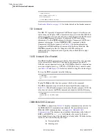
Page 393: ...y Compare these quantities against other devices of known accuracy The METER command is available at the serial ports and front panel display See Section 7 Communications and Section 8 Front Panel Ope...

Page 394: ...n software and serial communications cable SEL 751A Settings Sheets with settings appropriate to your application and protection design The ac and dc elementary schematics and wiring diagrams for this...

Page 395: ...ate relay terminals NOTE Make sure the current transformer secondary windings are shorted before they are disconnected from the relay a Disconnect the current transformer and voltage transformer if pr...

Page 396: ...rectly The expected magnitude is applied current CTRN The expected phase angle is zero 0 Step 17 Verify control input connections Using the front panel MAIN Targets Row 17 function check the control i...

Page 397: ...hould be balanced have proper phase rotation and have the appropriate phase relationship to the phase voltages Step 25 If your relay is equipped with voltage inputs check the following Phase voltage m...

Page 398: ...h the PHROT setting Refer to Figure 10 1 Step 4 Apply the appropriate magnitude for each phase current as shown in Column 1 of Table 10 3 Table 10 2 Phase Current Measuring Accuracy I Applied A second...

Page 399: ...values Step 4 Apply the current and voltage quantities shown in Column 1 of Table 10 4 Values are given for PHROT ABC and PHROT ACB Step 5 Use the front panel METER function or the serial port MET co...

Page 400: ...alues are given for PHROT ABC and PHROT ACB Step 5 Use the front panel METER or the serial port MET command to verify the results PHROT ACB Ia 2 5 26 Ib 2 5 94 Ic 2 5 146 Expected P 0 4523 CTR PTR Exp...

Page 401: ...surement by the detector is used to determine the integrity of the point sensor AFD loop and report PASS FAIL status 2 Bare Fiber Sensor AFD Self Test The bare fiber sensor is basically a loop startin...

Page 402: ...e appropriate TOL element relay word bit picks up and drops out as expected The arc flash test can also be captured as a CEV event report by triggering the event report with the TOLn relay word bit Th...

Page 403: ...atus Use the front panel STATUS or serial port STATUS command to ver ify that the relay self tests have not detected any WARN or FAIL con ditions Arc Flash Detection AFD Status Use the serial port AFT...

Page 404: ...rnal RAM power up Performs a read write test on system RAM Yes Latched Status Fail RAM Failure External RAM run time Performs a read write test on system RAM Yes Latched Status Fail RAM Failure Intern...

Page 405: ...9 V Yes Latched Status Fail 1 8 V Failure 3 3 V Fail Monitor 3 3 V power supply 3 07 to 3 53 V Yes Latched Status Fail 3 3 V Failure 5 V Fail Monitor 5 V power supply 4 65 to 5 35 V Yes Latched Status...

Page 406: ...the display The relay is de energized Verify input power and fuse continuity The relay does not accurately measure voltages or currents Wiring error Verify input wiring Incorrect CTR CTRN or PTR setti...

Page 407: ...istance We appreciate your interest in SEL products and services If you have questions or comments please contact us at Schweitzer Engineering Laboratories Inc 2350 NE Hopkins Court Pullman WA 99163 5...

Page 408: ...This page intentionally left blank...
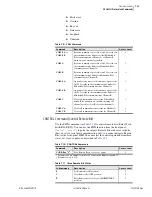
Page 409: ...is listed first Table A 1 400 Series Firmware Revision History Firmware Identification FID Number Summary of Revisions Manual Date Code SEL 751A R402 V0 Z006003 D20100129 Added faulted phase Identific...

Page 410: ...ent 50PAF and 50NAF protec tion options Added arc flash light measurements to the CEV report and created a meter light report 20090109 Added DNP3 serial and LAN WAN protocol options Added synchrophaso...

Page 411: ...ge input VS based over and undervoltage elements 27S 59S Added new Ethernet port options single fiber optic Ethernet dual fiber optic or copper Ethernet ports with FAILOVER or SWITCH modes Added capab...

Page 412: ...Table A 6 lists the instruction manual release dates and a description of modifications The most recent instruction manual revisions are listed at the top SEL 751A R102 V0 Z002001 D20080121 Corrected...

Page 413: ...Card and 1 4 STA Command Response Communications Card DeviceNet Protocol Section 2 Updated Figure 2 7 Pins for Password Breaker Control and SELBOOT Jumper to show jumper locations on updated processor...

Page 414: ...g MET PM Added arc flash light metering MET L Added description and settings for breaker monitor function Section 6 Updated settings sheets for the additions listed under Section 4 above Section 7 Add...

Page 415: ...ew additions Section 4 Added reclosing control description and settings Added synchronism check description and settings Revised VNOM 27P1P 27P2P and 50 elements settings ranges Added new Ethernet por...

Page 416: ...ted by ACSELERATOR Architect revision R 1 1 69 0 Added Table E 7 ICD Logical Nodes Summary Updated Tables E 10 Logical Device PRO Protection E 11 Logical Device MET Metering E 12 Logical Device CON Co...

Page 417: ...Settings Sheets Section 7 Updated Table 7 1 SEL 751A Communication Port Interfaces Table 7 31 PASSWORD Command and Table 7 32 PAS Command Format Section 8 Updated Configurable Label information in Pro...

Page 418: ...This page intentionally left blank...

Page 419: ...file e g r400751A s19 or r400751A z19 Upgrade Instructions The instructions below assume you have a working knowledge of your personal computer terminal emulation software In particular you must be ab...

Page 420: ...that contains the new firmware e g r400751A s19 or r400751A z19 The file transfer takes approximately 10 15 minutes at 115200 baud and with 1k Xmodem transfer protocol After the transfer is complete...

Page 421: ...t This procedure assumes that IEC 61850 was operational with a valid CID file immediately before initiating the relay firmware upgrade a Establish an FTP Connection to the relay Ethernet port b Open t...

Page 422: ...version Once converted downloaded and processed the valid CID file allows the relay to re enable the IEC 61850 protocol d In the Telnet session type GOO and press Enter e View the GOOSE status and ver...

Page 423: ...of the bytes that precede the checksum field in the message The program that uses the data can detect transmission errors in the message by summing the characters of the received message and comparin...

Page 424: ...configuration by using a single data stream and SEL Compressed ASCII and binary messages In subsequent operations the SEL communications processor uses the binary data stream for Fast Meter and Fast O...

Page 425: ...o databases for SCADA HMI and other data consumers Access to the IEDs for engineering functions including configuration report data retrieval and control through local serial remote dial in and Ethern...

Page 426: ...an programming in C or another general purpose computer language SEL communications processors offer the protocol interfaces listed in Table C 3 Table C 3 SEL Communications Processors Protocol Interf...

Page 427: ...ation data from a communications processor than for many conversations required to collect data directly from each individual IED You can further reduce data latency by connecting any SEL communicatio...

Page 428: ...man Machine Interface Figure C 3 Enhancing Multidrop Networks With SEL Communications Processors In this example the SEL communications processor provides the following enhancements when compared to a...

Page 429: ...processor Table C 4 SEL Communications Processor Port 1 Settings Setting Name Setting Description DEVICE S Connected device is an SEL device CONFIG Y Allow autoconfiguration for this device PORTID Re...

Page 430: ...ications Processor Port 1 Automatic Messaging Settings Setting Name Setting Description AUTOBUF Y Save unsolicited messages STARTUP ACC nOTTER n Automatically log in at Access Level 1 SEND_OPER Y Send...

Page 431: ...mber Use the VIE n D1 command to view these data Table C 8 Communications Processor METER Region Map Item Starting Address Type _YEAR 2000h int DAY_OF_YEAR 2001h int TIME ms 2002h int 2 MONTH 2004h ch...

Page 432: ...unications processor it automatically sets RB01 in the SEL 751A Breaker bit BR1 operates differently than remote bits There is one breaker bit in the SEL 751A For Circuit Breaker 1 when you set BR1 th...

Page 433: ...gion 3 The type field indicates the data type and size The type int is a 16 bit integer The type float is a 32 bit IEEE floating point number Table C 10 Communications Processor DEMAND Region Map Item...

Page 434: ...This page intentionally left blank...

Page 435: ...rol applications Version 3 0 of the protocol has also become popular for local substation data collection DNP3 is one of the protocols included in the IEEE Recommended Practice for Data Communication...

Page 436: ...time synchronization or even all data within the DNP3 device If there can be more than one instance of a type of object then each instance of the object includes an index that makes it unique For exa...

Page 437: ...ures optimize use of bandwidth and maximize performance over a connection of any speed DNP3 event data collection eliminates the need to use bandwidth to transmit values that have not changed Event da...

Page 438: ...for new DNP3 devices but is often included for interoperability with older DNP3 master implementations The control device output block code selection specifies either a latch or pulse operation on th...

Page 439: ...icited reporting results in network medium contention if you do not design your serial network as a star topology of point to point connections or use carrier detection on a multidrop network To avoid...

Page 440: ...master for polling as specified Table D 4 TCP UDP Selection Guidelines Use in the case of TCP UDP Most situations X Non broadcast or multicast X Mesh Topology WAN X Broadcast X Multicast X High reliab...

Page 441: ...s features For example you might place high priority points in event class 1 and set it with low thresholds NUMEVEn and AGEEVEn settings so that changes to these points will be sent to the master quic...

Page 442: ...ignal control and data transmission see Figure D 2 For example an EIA 485 transceiver typically requires 10 to 20 ms to change from receive to transmit If you set the pre delay to 30 ms you will avoid...

Page 443: ...u can send some decimal values using this technique You must also configure the master to perform the appropriate division on the incoming value to display it properly You can set the default analog v...

Page 444: ...message from the local modem and for assertion of the device CTS line before continuing the DNP transaction This requires a connection from the modem DCD to the device CTS line NOTE Contact SEL for i...

Page 445: ...3 1 ECLASSC1 Class for counter event data 0 disables 0 3 0 ECLASSA1 Class for analog event data 0 disables 0 3 2 DECPLA1 Decimal places scaling for Current data 0 3 1 DECPLV1 Decimal places scaling f...

Page 446: ...0 PREDLYb Settle time from RTS on to TX Off disables PSTDLY OFF 0 00 30 00 0 00 PSTDLYb Settle time from TX to RTS off hidden if PREDLY set to Off 0 00 30 00 0 00 a Available only on Ethernet ports b...

Page 447: ...your application The SEL 751A uses object and point labels rather than point indices to streamline the remapping process This enables you to quickly create a custom map without having to search for ea...

Page 448: ..._31 RB32 Analog Input Map AI_00 IA_MAG AI_01 IB_MAG AI_02 IC_MAG AI_95 FREQ AI_96 P AI_97 Q AI_98 S AI_99 PF Analog Output Map AO_00 GROUP AO_01 NOOP AO_02 NA AO_29 NA AO_30 NOOP AO_31 NOOP Counter Ma...

Page 449: ...BEL EVENT CLASS DEADBAND 0 SC01 0 1 1 SC02 0 1 2 SC03 0 1 29 SC30 0 1 30 SC31 0 1 31 SC32 0 1 Analog Inputs INDEX POINT LABEL EVENT CLASS SCALE FACTOR DEADBAND 0 IA_MAG 2 10 0000 1000 1 IB_MAG 2 10 00...

Page 450: ...point customization is not required but class scaling DECPLA DECPLV and DECPLM and dead band ANADBA ANADBV and ANADBM settings are applied to indices that do not have per point entries Unlike per poi...

Page 451: ...ave changes Y N Y Enter Figure D 5 Sample Custom DNP3 AI Map Settings You may also use ACSELERATOR QuickSet to enter the above AI map settings as shown in the screen capture in Figure D 6 You can ente...

Page 452: ...The SET DNP x CO_00 Enter command allows you to populate the DNP counter map with per point dead bands Entering these settings is similar to defining the analog input map settings You can use the com...

Page 453: ...Label Name 23 characters BO_02 NA RB03 RB04 Enter DNP Binary Output Label Name 23 characters BO_03 NA RB05 RB06 Enter DNP Binary Output Label Name 23 characters BO_04 NA end Enter Figure D 8 Sample Cu...

Page 454: ...plication layer retries None Requires application layer confirmation When reporting Event Data Data link confirm time out Configurable Complete application fragment time out None Application confirm t...

Page 455: ...nput Change With Relative Time 1 6 7 8 129 17 28 10 0 Binary Output All Variations 1 0 1 6 7 8 10 1 Binary Output 10 2e Binary Output Status 1 0 1 6 7 8 129 0 1 12 0 Control Block All Variations 12 1...

Page 456: ...23 2 16 Bit Frozen Counter Event Without Time 23 3 32 Bit Frozen Delta Counter Event Without Time 23 4 16 Bit Frozen Delta Counter Event Without Time 23 5 32 Bit Frozen Counter Event With Time 23 6 1...

Page 457: ...ut Time 33 3 32 Bit Frozen Analog Event With Time 33 4 16 Bit Frozen Analog Event With Time 33 5 Short Floating Point Frozen Analog Event 33 6 Long Floating Point Frozen Analog Event 33 7 Short Floati...

Page 458: ...ata 1 20 21 6 7 8 60 4 Class 3 Data 1 20 21 6 7 8 70 1 File Identifier 70 2 Authentication Object 70 3 File Command Object 70 4 File Command Status Object 70 5 File Transport Object 70 6 File Transpor...

Page 459: ...13 cold start 14 warm start 23 delay measurement 13 14 23 a Supported in requests from master b May generate in response to master c Decimal d Hexadecimal e Default variation Table D 11 SEL 751A DNP O...

Page 460: ...ata Map Sheet 2 of 2 Object Labels Description NOTE Although not shown as part of the reference maps you may use any Relay Word bit label when creating custom maps Table D 13 DNP3 Default Data Map Obj...

Page 461: ...command messages The SEL 751A assigns some special operations to the code portion of the control device output block command The example in Table D 14 demonstrates how you may use this functionality f...

Page 462: ...This page intentionally left blank...
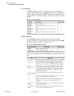
Page 463: ...ta maps as Modbus RTU Enable Modbus RTU protocol with the serial port settings When Modbus RTU protocol is enabled the relay switches the port to Modbus RTU protocol and deactivates the ASCII protocol...

Page 464: ...query command for any reason it sends an error response Otherwise the slave device response is formatted similarly to the query and includes the slave address function code data if applicable and a c...

Page 465: ...d the status of as many as 2000 bits per query using the fields shown in Table E 4 Note that the SEL 751A coil addresses start at 0 e g Coil 1 is located at address zero The coil status is packed one...

Page 466: ...at 0 e g Input 1 is located at address zero The input status is packed one input per bit of the data field The LSB of the first data byte contains the starting input address in the query The other in...

Page 467: ...lowing format 1 byte Slave Address 1 byte Function Code 02h 1 byte Bytes of data n n bytes Data 2 bytes CRC 16 Table E 7 02h SEL 751A Inputs Sheet 1 of 4 Coil Address Decimal Function Code Supported C...

Page 468: ...ay Element Status Row 39 320 327 2 Relay Element Status Row 40 328 335 2 Relay Element Status Row 41 336 343 2 Relay Element Status Row 42 344 351 2 Relay Element Status Row 43 352 359 2 Relay Element...

Page 469: ...y Element Status Row 79 640 647 2 Relay Element Status Row 80 648 655 2 Relay Element Status Row 81 656 663 2 Relay Element Status Row 82 664 671 2 Relay Element Status Row 83 672 679 2 Relay Element...

Page 470: ...880 887 2 Relay Element Status Row 110 888 895 2 Relay Element Status Row 111 896 903 2 Relay Element Status Row 112 904 911 2 Relay Element Status Row 113 912 919 2 Relay Element Status Row 114 920...

Page 471: ...e Slave Address 1 byte Function Code 03h 2 bytes Starting Register Address 2 bytes Number of Registers to Read 2 bytes CRC 16 A successful response from the slave will have the following format 1 byte...

Page 472: ...sponses to 04h Read Input Register Query Errors Error Error Code Returned Communication Counter Increments Illegal register to read Illegal Data Address 02h Invalid Address Illegal number of registers...

Page 473: ...ved 16 01 05 Reserved 17 01 05 Reserved 18 01 05 Reserved 19 01 05 Pulse OUT501 1 second 20 01 05 Pulse OUT502 1 second 21 01 05 Pulse OUT503 1 second 22 01 05 Pulse OUT504 1 second 23 01 05 Reserved...

Page 474: ...RB27 54 01 05 RB28 55 01 05 RB29 56 01 05 RB30 57 01 05 RB31 58 01 05 RB32 59 01 05 Pulse RB01a 60 01 05 Pulse RB02a 61 01 05 Pulse RB03a 62 01 05 Pulse RB04a 63 01 05 Pulse RB05a 64 01 05 Pulse RB06a...

Page 475: ...In Table E 16 the command response is identical to the command required by the master 74 01 05 Pulse RB16a 75 01 05 Pulse RB17a 76 01 05 Pulse RB18a 77 01 05 Pulse RB19a 78 01 05 Pulse RB20a 79 01 05...

Page 476: ...6h 2 bytes Register Address 2 bytes Data 2 bytes CRC 16 Table E 17 Responses to 06h Preset Single Register Query Errors Error Error Code Returned Communication Counter Increments Illegal register addr...

Page 477: ...lue 03h Bad Packet Format Illegal Write Invalid register data value Illegal Data Value 03h Illegal Write Table E 20 60h Read Parameter Information Command Bytes Field Queries from the master must have...

Page 478: ...extend the descriptor table Table E 22 60h Read Parameter Conversion Field Definition Conversion Value Type Multiplier Divisor Offset Base 0 Boolean 1 1 0 1 1 Unsigned Integer 1 1 0 1 2 Unsigned Inte...

Page 479: ...Text Command Bytes Field Queries from the master must have the following format 1 byte Slave Address 1 byte Function Code 61h 2 bytes Parameter Number 2 bytes CRC 16 A successful response from the sla...

Page 480: ...Parameter Enumeration Text Query Error Messages Error Error Code Returned Communication Counter Increments Illegal parameter to read Illegal Address 02h Invalid Address Illegal enumeration in index Il...

Page 481: ...ny of the settings listed in the Modbus Register Map Table E 32 can be changed The high and low limits provided in the table might cover a wider range than what is acceptable by the particular model o...

Page 482: ...ch of the outputs User Defined Modbus Data Region and SET M Command The SEL 751A Modbus Register Map defines an area of 125 contiguous addresses whose contents are defined by 125 user settable address...

Page 483: ...0 726 RTD11 727 RTD12 728 RES_728 729 LSENS1 730 LSENS2 731 LSENS3 732 LSENS4 733 RES_733 734 RES_734 735 RES_735 736 RES_736 737 RES_737 738 RES_738 739 VSRMS 740 IARMS 741 IBRMS 742 ICRMS 743 INRMS...

Page 484: ...9 RTD7MN 1010 RTD7N_S 1011 RTD7NMN 1012 RTD7N_H 1013 RTD7N_D 1014 RTD7NMO 1015 RTD7N_Y 1016 RTD8MX 1017 RTD8X_S 1018 RTD8XMN 1019 RTD8X_H 1020 RTD8X_D 1021 RTD8XMO 1022 RTD8X_Y 1023 RTD8MN 1024 RTD8N_...

Page 485: ...72 AI404N_S 1273 AI404NMN 1274 AI404N_H 1275 AI404N_D 1276 AI404NMO 1277 AI404N_Y 1278 AI405MXH 1279 AI405MXL 1280 AI405X_S 1281 AI405XMN 1282 AI405X_H 1283 AI405X_D 1284 AI405XMO 1285 AI405X_Y 1286 A...

Page 486: ...AI504L 1533 AI505H 1534 AI505L 1535 AI506H 1536 AI506L 1537 AI507H 1538 AI507L 1539 AI508H 1540 AI508L 1541 RES_1541 1542 RES_1542 1543 RES_1543 1544 RES_1544 1545 RES_1545 1546 RES_1546 1547 MV01H 15...

Page 487: ...1 RES_1801 1802 RES_1802 1803 RES_1803 1804 RES_1804 1805 ROW_0 1806 ROW_1 1807 ROW_2 1808 ROW_3 1809 ROW_4 1810 ROW_5 1811 ROW_6 1812 ROW_7 1813 ROW_8 1814 ROW_9 1815 ROW_10 1816 ROW_11 1817 ROW_12 1...

Page 488: ...lists the data available in the Modbus interface and its description range and scaling information The table also shows the parameter number for access using the DeviceNet interface The DeviceNet par...

Page 489: ...RATIO F 0 99 0 0 01 378 279 R W XFMR CONNECTION 0 1 0 379 0 DELTA 1 WYE 280 R W LINE VOLTAGE V 10000 44000 12000 0 01 380 281 R W SINGLE V INPUT 0 1 0 381 0 N 1 Y 282 283 R Reservedc 0 0 0 382 383 Max...

Page 490: ...1 Y 309 R W NEUT OC TRIP L4 A 10 10000 200 0 01 409 310 R W NEUT OC TRIP L4 mA 1 10000 100 0 1 410 311 R W NEUT OC L4 DLY sec 0 500 50 0 01 411 Residual Overcurrent 312 R W RES OC L1 EN 0 1 0 412 0 N...

Page 491: ...0 01 435 Phase Time Overcurrent 336 R W PHA TOC TRIP EN 0 1 1 436 0 N 1 Y 337 R W PHA TOC TRIP LVL A 10 1600 120 0 01 437 338 R W PHA TOC CURVE 0 9 2 438 0 U1 1 U2 2 U3 3 U4 4 U5 5 C1 6 C2 7 C3 8 C4...

Page 492: ...IME sec 0 100 0 0 01 455 356 R W PHC MIN RESP TIM sec 0 100 0 0 01 456 Maximum Phase Time Overcurrent 357 R W TOC TRIP L1 EN 0 1 1 457 0 N 1 Y 358 R W TOC TRIP LVL1 A 10 1600 120 0 01 458 359 R W TOC...

Page 493: ...120 0 01 472 373 R W NSTOC CURVE SEL 0 9 2 1 473 0 U1 1 U2 2 U3 3 U4 4 U5 5 C1 6 C2 7 C3 8 C4 9 C5 374 R W NSTOC TIME DIAL 5 1500 300 0 01 474 375 R W NSTOC EM RST DLY 0 1 0 475 0 N 1 Y 376 R W NSTOC...

Page 494: ...IM DL2 5 1500 150 0 01 490 391 R W NEU EM RST DLAY2 0 1 0 491 0 N 1 Y 392 R W NEUT CONST TIME2 sec 0 100 0 0 01 492 393 R W NEU MIN RESP T2 sec 0 100 0 0 01 493 Residual Time Overcurrent 394 R W RES T...

Page 495: ...TD Settings 411 R W RTD ENABLE 0 2 0 511 0 NONE 1 INT 2 EXT 412 R W RTD1 LOCATION 0 4 0 512 0 OFF 1 WDG 2 BRG 3 AMB 4 OTH 413 R W RTD1 TYPE 0 3 0 513 0 PT100 1 NI100 2 NI120 3 CU10 414 R W RTD1 TRIP L...

Page 496: ...CU10 426 R W RTD4 TRIP LEVEL degC 0 250 0 1 526 0 Off 427 R W RTD4 WARN LEVEL degC 0 250 0 1 527 0 Off 428 R W RTD5 LOCATION 0 4 0 1 528 0 OFF 1 WDG 2 BRG 3 AMB 4 OTH 429 R W RTD5 TYPE 0 3 0 1 529 0...

Page 497: ...RTD8 TYPE 0 3 0 1 541 0 PT100 1 NI100 2 NI120 3 CU10 442 R W RTD8 TRIP LEVEL degC 0 250 0 1 542 0 Off 443 R W RTD8 WARN LEVEL degC 0 250 0 1 543 0 Off 444 R W RTD9 LOCATION 0 4 0 1 544 0 OFF 1 WDG 2...

Page 498: ...YPE 0 3 0 1 557 0 PT100 1 NI100 2 NI120 3 CU10 458 R W RTD12 TRIP LEVEL degC 0 250 0 1 558 0 Off 459 R W RTD12 WARN LEVEL degC 0 250 0 1 559 0 Off 460 R W WIND TRIP VOTING 0 1 0 1 560 0 N 1 Y 461 R W...

Page 499: ...0 583 0 N 1 Y 484 R W OVS LEVEL2 V 200 30000 30000 0 01 584 485 R W OVS DELAY2 sec 0 1200 5 0 1 585 Reclosing Control 486 R W ENABLE RECLOSER 0 4 0 1 586 487 R W OPEN INTERVAL1 I sec 0 3000 5 1 587 4...

Page 500: ...Hz 2000 7000 6000 0 01 614 515 R W FREQ1 TRIP DELAY sec 0 2400 10 0 1 615 516 R W FREQ2 TRIP ENABL 0 1 0 616 0 N 1 Y 517 R W FREQ2 TRIP LEVEL Hz 2000 7000 6000 0 01 617 518 R W FREQ2 TRIP DELAY sec 0...

Page 501: ...S 0 32 0 1 644 545 R W MATH VARIABLES 0 32 0 1 645 546 550 R Reservedc 0 0 0 646 650 Output Contacts 0 N 1 Y 551 R W OUT101 FAIL SAFE 0 1 1 651 552 R W OUT102 FAIL SAFE 0 1 0 652 553 R W OUT103 FAIL S...

Page 502: ...LCD TIMEOUT min 0 30 15 1 683 0 Off 584 R W LCD CONTRAST 1 8 5 1 684 585 R W CLOSE RESET LEDS 0 1 1 685 0 N 1 Y 586 R W FP AUTOMESSAGES 0 1 0 686 0 OVERRIDE 1 ROTATING 587 590 R Reservedc 0 0 0 687 69...

Page 503: ...S 0 2 0 721 622 R 2 5V STATUS 0 2 0 722 623 R 3 75V STATUS 0 2 0 723 624 R 1 25V STATUS 0 2 0 724 625 R 5 0V STATUS 0 2 0 725 626 R CLK_BAT STATUS 0 2 0 726 627 R CT BOARD STATUS 0 2 0 727 628 R CARD...

Page 504: ...0 0 1 766 Voltage Data 667 R VAB V 0 65535 0 1 767 668 R VAB ANGLE deg 1800 1800 0 0 1 768 669 R VBC V 0 65535 0 1 769 670 R VBC ANGLE deg 1800 1800 0 0 1 770 671 R VCA V 0 65535 0 1 771 672 R VCA ANG...

Page 505: ...9 2000 1 803 704 R MWH3PI HI MWhr 0 65535 0 0 1 804 705 R MWH3PI LO MWhr 0 65535 0 0 1 805 706 711 R Reservedc 0 0 0 806 811 RTD Data 712 R MAX WINDING RTD degC 32768 32767 0 1 812 7FFFh Open 8000h Sh...

Page 506: ...862 763 R IA MIN DAY yy 2000 9999 2000 1 863 764 R IB MAX A 0 65535 0 1 864 765 R IB MAX TIME ss 0 5999 0 0 01 865 766 R IB MAX TIME mm 0 59 0 1 866 767 R IB MAX TIME hh 0 23 0 1 867 768 R IB MAX DAY...

Page 507: ...9999 2000 1 905 806 R IG MAX A 0 65535 0 1 906 807 R IG MAX TIME ss 0 5999 0 0 01 907 808 R IG MAX TIME mm 0 59 0 1 908 809 R IG MAX TIME hh 0 23 0 1 909 810 R IG MAX DAY dd 1 31 1 1 910 811 R IG MAX...

Page 508: ...VC MAX V 0 65535 0 1 948 849 R VCA VC MX TIM ss 0 5999 0 0 01 949 850 R VCA VC MX TIM mm 0 59 0 1 950 851 R VCA VC MX TIM hh 0 23 0 1 951 852 R VCA VC MX DAY dd 1 31 1 1 952 853 R VCA VC MX DAY mm 1 1...

Page 509: ...VA3P MX TIM ss 0 5999 0 0 01 991 892 R KVA3P MX TIM mm 0 59 0 1 992 893 R KVA3P MX TIM hh 0 23 0 1 993 894 R KVA3P MX DAY dd 1 31 1 1 994 895 R KVA3P MX DAY mm 1 12 1 1 995 896 R KVA3P MX DAY yy 2000...

Page 510: ...999 0 0 01 1033 934 R RTD2 MX TIM mm 0 59 0 1 1034 935 R RTD2 MX TIM hh 0 23 0 1 1035 936 R RTD2 MX DAY dd 1 31 1 1 1036 937 R RTD2 MX DAY mm 1 12 1 1 1037 938 R RTD2 MX DAY yy 2000 9999 2000 1 1038 9...

Page 511: ...D5 MX TIM mm 0 59 0 1 1076 977 R RTD5 MX TIM hh 0 23 0 1 1077 978 R RTD5 MX DAY dd 1 31 1 1 1078 979 R RTD5 MX DAY mm 1 12 1 1 1079 980 R RTD5 MX DAY yy 2000 9999 2000 1 1080 981 R RTD5 MIN degC 32768...

Page 512: ...MX TIM hh 0 23 0 1 1119 1020 R RTD8 MX DAY dd 1 31 1 1 1120 1021 R RTD8 MX DAY mm 1 12 1 1 1121 1022 R RTD8 MX DAY yy 2000 9999 2000 1 1122 1023 R RTD8 MIN degC 32768 32767 0 1 1123 1024 R RTD8 MN TI...

Page 513: ...X TIM hh 0 23 0 1 1161 1062 R RTD11 MX DAY dd 1 31 1 1 1162 1063 R RTD11 MX DAY mm 1 12 1 1 1163 1064 R RTD11 MX DAY yy 2000 9999 2000 1 1164 1065 R RTD11 MIN degC 32768 32767 0 1 1165 1066 R RTD11 MN...

Page 514: ...MX HI EU 32768 32767 0 0 001 1202 1103 R AI302 MX LO EU 32768 32767 0 0 001 1203 1104 R AI302 MX TIM ss 0 5999 0 0 01 1204 1105 R AI302 MX TIM mm 0 59 0 1 1205 1106 R AI302 MX TIM hh 0 23 0 1 1206 110...

Page 515: ...LO EU 32768 32767 0 0 001 1243 1144 R AI304 MN TIM ss 0 5999 0 0 01 1244 1145 R AI304 MN TIM mm 0 59 0 1 1245 1146 R AI304 MN TIM hh 0 23 0 1 1246 1147 R AI304 MN DAY dd 1 31 1 1 1247 1148 R AI304 MN...

Page 516: ...001 1283 1184 R AI307 MX TIM ss 0 5999 0 0 01 1284 1185 R AI307 MX TIM mm 0 59 0 1 1285 1186 R AI307 MX TIM hh 0 23 0 1 1286 1187 R AI307 MX DAY dd 1 31 1 1 1287 1188 R AI307 MX DAY mm 1 12 1 1 1288 1...

Page 517: ...8 32767 0 0 001 1323 1224 R AI401 MN TIM ss 0 5999 0 0 01 1324 1225 R AI401 MN TIM mm 0 59 0 1 1325 1226 R AI401 MN TIM hh 0 23 0 1 1326 1227 R AI401 MN DAY dd 1 31 1 1 1327 1228 R AI401 MN DAY mm 1 1...

Page 518: ...001 1363 1264 R AI404 MX TIM ss 0 5999 0 0 01 1364 1265 R AI404 MX TIM mm 0 59 0 1 1365 1266 R AI404 MX TIM hh 0 23 0 1 1366 1267 R AI404 MX DAY dd 1 31 1 1 1367 1268 R AI404 MX DAY mm 1 12 1 1 1368 1...

Page 519: ...001 1403 1304 R AI406 MN TIM ss 0 5999 0 0 01 1404 1305 R AI406 MN TIM mm 0 59 0 1 1405 1306 R AI406 MN TIM hh 0 23 0 1 1406 1307 R AI406 MN DAY dd 1 31 1 1 1407 1308 R AI406 MN DAY mm 1 12 1 1 1408 1...

Page 520: ...767 0 0 001 1443 1344 R AI501 MX TIM ss 0 5999 0 0 01 1444 1345 R AI501 MX TIM mm 0 59 0 1 1445 1346 R AI501 MX TIM hh 0 23 0 1 1446 1347 R AI501 MX DAY dd 1 31 1 1 1447 1348 R AI501 MX DAY mm 1 12 1...

Page 521: ...001 1483 1384 R AI503 MN TIM ss 0 5999 0 0 01 1484 1385 R AI503 MN TIM mm 0 59 0 1 1485 1386 R AI503 MN TIM hh 0 23 0 1 1486 1387 R AI503 MN DAY dd 1 31 1 1 1487 1388 R AI503 MN DAY mm 1 12 1 1 1488 1...

Page 522: ...001 1523 1424 R AI506 MX TIM ss 0 5999 0 0 01 1524 1425 R AI506 MX TIM mm 0 59 0 1 1525 1426 R AI506 MX TIM hh 0 23 0 1 1526 1427 R AI506 MX DAY dd 1 31 1 1 1527 1428 R AI506 MX DAY mm 1 12 1 1 1528 1...

Page 523: ...hh 0 23 0 1 1566 1467 R AI508 MN DAY dd 1 31 1 1 1567 1468 R AI508 MN DAY mm 1 12 1 1 1568 1469 R AI508 MN DAY yy 2000 9999 2000 1 1569 MAX MIN RST Data 1470 R MX MN RST TIM ss 0 5999 0 0 01 1570 147...

Page 524: ...1512 R AI402 LO EU 32768 32767 0 0 001 1612 1513 R AI402 HI EU 32768 32767 0 0 001 1613 1514 R AI403 LO EU 32768 32767 0 0 001 1614 1515 R AI404 HI EU 32768 32767 0 0 001 1615 1516 R AI404 LO EU 32768...

Page 525: ...2768 32767 0 0 01 1658 1559 R MV07 HI 32768 32767 0 0 01 1659 1560 R MV07 LO 32768 32767 0 0 01 1660 1561 R MV08 HI 32768 32767 0 0 01 1661 1562 R MV08 LO 32768 32767 0 0 01 1662 1563 R MV09 HI 32768...

Page 526: ...768 32767 0 0 01 1699 1600 R MV27 LO 32768 32767 0 0 01 1700 1601 R MV28 HI 32768 32767 0 0 01 1701 1602 R MV28 LO 32768 32767 0 0 01 1702 1603 R MV29 HI 32768 32767 0 0 01 1703 1604 R MV29 LO 32768 3...

Page 527: ...1 1773 1674 R VS MIN 0 65535 0 1 1774 1675 R VS MIN TIME ss 0 5999 0 0 01 1775 1676 R VS MIN TIME mm 0 59 0 1 1776 1677 R VS MIN TIME hh 0 23 0 1 1777 1678 R VS MIN DAY dd 1 31 1 1 1778 1679 R VS MIN...

Page 528: ...RIP 2 PHASE B1 50 TRIP 3 PHASE C1 50 TRIP 4 PHASE 50 TRIP 5 GND NEUT 50 TRIP 6 NEG SEQ 50 TRIP 7 PHASE A 51 TRIP 8 PHASE B 51 TRIP 9 PHASE C 51 TRIP 10 PHASE 51 TRIP 11 GND NEUT 51 TRIP 12 NEG SEQ 51...

Page 529: ..._Led Bit 3 T03_Led Bit 4 T02_Led Bit 5 T01_Led Bit 6 Trip Bit 7 Enabled 1756 R EVENT IA A 0 65535 0 1 1856 1757 R EVENT IB A 0 65535 0 1 1857 1758 R EVENT IC A 0 65535 0 1 1858 1759 R EVENT IN A 0 655...

Page 530: ...81 R TRIP STATUS HI 0 65535 0 1 1881 Bit 0 POWER FACTOR 55 Bit 1 FREQUENCY 81D1 Bit 2 FREQUENCY 81D2 Bit 3 RTD OTHER Bit 4 RTD AMBIENT Bit 5 RTD WIND BEAR Bit 6 RTD ERROR Bit 7 POWER ELEMENTS Bit 8 CO...

Page 531: ...0 1791 R INVALID ADDR 0 65535 0 1 1891 1792 R BAD CRC 0 65535 0 1 1892 1793 R UART ERROR 0 65535 0 1 1893 1794 R ILLEGAL FUNCTION 0 65535 0 1 1894 1795 R ILLEGAL REGISTER 0 65535 0 1 1895 1796 R ILLEG...

Page 532: ...it 1 50G3P Bit 2 50G2P Bit 3 50G1P Bit 4 50N4P Bit 5 50N3P Bit 6 50N2P Bit 7 50N1P 1810 R ROW 5 0 255 0 1 1910 Bit 0 50G4T Bit 1 50G3T Bit 2 50G2T Bit 3 50G1T Bit 4 50N4T Bit 5 50N3T Bit 6 50N2T Bit 7...

Page 533: ...3P59 Bit 2 59P2T Bit 3 59P2 Bit 4 59P1T Bit 5 59P1 Bit 6 27P2T Bit 7 27P2 1816 R ROW 11 0 255 0 1 1916 Bit 0 55T Bit 1 55A Bit 2 81D6T Bit 3 81D5T Bit 4 81D4T Bit 5 81D3T Bit 6 81D2T Bit 7 81D1T 1817...

Page 534: ...024 1925 1947 R Reservedc 0 0 0 2025 2047 Extra Settings 1948 R W BREAKER MONITOR 0 1 1 2048 0 N 1 Y 1949 R W CL OPN OPS SETP1 0 65000 10000 1 2049 1950 R W CL OPN OPS SETP2 0 65000 150 1 2050 1951 R...

Page 535: ...101_2 1 301_2 2 401_2 1971 R W EN SYNCHRO PHSOR 0 1 0 2071 0 N 1 Y 1972 R W MESSAGES PER SEC 0 3 3 2072 0 1 1 2 2 5 3 10 1973 R W PMU HARDWARE ID 1 65534 1 1 2073 1974 R W VOLTAGE DATA SET 0 2 0 2074...

Page 536: ...0 1200 50 0 1 2104 2005 R W NSQ OV TRIP1 EBL 0 1 0 2105 0 N 1 Y 2006 R W NSQ OV TRIP1 LVL xVnm 2 120 110 0 01 2106 2007 R W NSQ OV TRIP1 DLY sec 0 1200 5 0 1 2107 2008 R W NSQ OV TRIP2 EBL 0 1 0 2108...

Page 537: ...R W 81R4 TREND 0 2 2 2131 0 INC 1 DEC 2 ABS 2032 R W 81R4 TRIP DELAY sec 10 6000 100 0 01 2132 2033 R W 81R4 DO DELAY sec 0 6000 0 0 01 2133 2034 R W DEMAND MTR 0 1 0 2134 0 THM 1 ROL 2035 R W DEM TIM...

Page 538: ...Bit 3 Return Status 0 1 Bit 4 DN Aux 1 Cmd Bit 5 DN Aux 2 Cmd Bit 6 DN Aux 3 Cmd Bit 7 DN Aux 4 Cmd Bit 8 DN Aux 5 Cmd Bit 9 DN Aux 6 Cmd Bit 10 DN Aux 7 Cmd Bit 11 DN Aux 8 Cmd Bit 12 DN Aux 9 Cmd Bi...

Page 539: ...6 IN404 Status Bit 3 IN7 IN501 Status Bit 4 IN8 IN502 Status Bit 5 IN9 IN503 Status Bit 6 IN10 IN504 Status Bit 7 Reserved Bit 8 AUX7 OUT501 Status Bit 9 AUX8 OUT502 Status Bit 10 AUX9 OUT503 Status B...

Page 540: ...506 Status Bit 6 IN25 IN507 Status Bit 7 IN26 IN508 Status Bit 8 Reserved Bit 9 Reserved Bit 10 Reserved Bit 11 Reserved Bit 12 Reserved Bit 13 Reserved Bit 14 Reserved Bit 15 Reserved PAR Group Indic...

Page 541: ...4 667 3024H R POWER DATA 685 689 685 3025H R ENERGY DATA 690 711 690 3026H R RTD DATA 712 728 712 3027H R LIGHT MTR DATA 729 738 729 3028H R RMS DATA 739 749 739 3029H R MAX MIN MTR DATA 750 917 750 3...

Page 542: ...0 na Bit 0 Explicit Cnxn Bit 1 I O Cnxn Bit 2 Explicit Fault Bit 3 I O Fault Bit 4 I O Idle Bit 5 Bit 15 Reserved 400AH not used 400BH R CONFIG PAR CKSUM 0 na 400CH R LANGUAGE CODE 0 na 0 English 1 F...

Page 543: ...Error Bit 10 Memory Not Available Bit 11 Settings Prep Error Bit 12 Setting Changes Disabled Bit 13 Memory Diag Error Bit 14 Reserved Bit 15 Reserved 4017H R ERROR ADDRESS 0 65535 0 4018H 401FH R Rese...

Page 544: ...This page intentionally left blank...
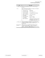
Page 545: ...ker Close CC bits can also be mapped from GOOSE receive messages using ACSELERATOR Architect SEL 5032 software Configuration Use FTP client software or ACSELERATOR Architect to transfer the Substation...

Page 546: ...1 The IEC 61850 document set available directly from the IEC at http www iec ch contains information necessary for successful implementation of this protocol SEL strongly recommends that anyone invol...

Page 547: ...tation IEDs as a series of objects called models or bricks The IEC working group has incorporated GOMSFE concepts into the standard with some modifications to terminology one change was the renaming o...

Page 548: ...rvices to a protocol that only provides access to simple data points via registers or index numbers MMS supports complex named objects and flexible services that enable mapping to IEC 61850 in a strai...

Page 549: ...on to the Virtual Bits the breaker control bits CC and OC can also be mapped to GOOSE receive messages File Services The Ethernet File System allows reading or writing data as files The File System su...

Page 550: ...sets For buffered reports connected clients may edit the report parameters shown in Table F 4 Similarly for unbuffered reports connected clients may edit the report parameters shown in Table F 5 Table...

Page 551: ...led each client has independent access to a copy of that URCB The Resv attribute is writable however the SEL 751A does not support reservations Writing any field of the URCB causes the client to obtai...

Page 552: ...ned as SER points i e programmed in the SER report the change is detected as the receipt of an SER record which contains the SER timestamp within the relay For all other Booleans or Bstrings the chang...

Page 553: ...er can also map a single GOOSE dataset to multiple GOOSE control blocks The SEL 751A will transmit all configured GOOSE immediately upon successful initialization If a GOOSE is not retriggered then fo...

Page 554: ...es Needs Commissioning this Boolean parameter of the incoming GOOSE is true Test Mode this Boolean parameter of the incoming GOOSE is true Decode Error the format of the incoming GOOSE is not as confi...

Page 555: ...her IEDs in the domain ACSELERATOR Architect has the capability to read other manufacturer s ICD and CID files enabling the engineer to map the data seamlessly into SEL IED logic See the ACSELERATOR A...

Page 556: ...u attempt to download a version 001 CID file to a relay with firmware R102 or later Architect will detect the incompatibility and offer to convert the existing file If you agree ACSELERATOR Architect...

Page 557: ...phase time overcurrent element 1 PRO P2T_PTOC2 P2TPTOC2 P2TPTOC2 P2TPTOC2 Maximum phase time overcurrent element 2 PRO N1T_PTOC3 N1TPTOC3 N1TPTOC3 N1TPTOC3 Neutral time overcurrent element 1 PRO N2T_...

Page 558: ...Zero Sequence Instantaneous Over voltage element 1 G2TPTOV7 Zero Sequence instantaneous over voltage element 2 Q1TPTOV8 Negative sequence instantaneous overvoltage element 1 Q2TPTOV9 Negative sequence...

Page 559: ...RORED BITS ANN TMBB_GGIO11 TMBBGGIO11 TMBBGGIO11 TMBBGGIO11 Channel B transmit MIRRORED BITS ANN MV_GGIO12 MVGGIO12 MVGGIO12 MVGGIO12 Math variable values ANN INPUTC_GGIO13 INCGGIO13 INCGGIO13 INCGGIO...

Page 560: ...l Monitoring Demand Metering Statistics MDST This LN shall be used for calculation of demand currents and energy in a three phase system This shall not be used for billing purposes Table F 9 Thermal M...

Page 561: ...m Phase to Phase Voltages O MinP2PV DEL Minimum Phase to Phase Voltages O Table F 11 MDST Class Attribute Name Type Explanation T M O LNName Shall be inherited from Logical Node Class see IEC 61850 7...

Page 562: ...P3P P3TPIOC3 Op general 50P3T P4TPIOC4 Str general 50P4P P4TPIOC4 Op general 50P4T N1TPIOC5 Str general 50N1P N1TPIOC5 Op general 50N1T N2TPIOC6 Str general 50N2P N2TPIOC6 Op general 50N2T N3TPIOC7 St...

Page 563: ...eral 51AP ATPTOC8 Op general 51AT BTPTOC9 Str general 51BP BTPTOC9 Op general 51BT CTPTOC10 Str general 51CP CTPTOC10 Op general 51CT D1TPTOF1 Str general 81D1T D1TPTOF1 Op general 81D1T D2TPTOF2 Str...

Page 564: ...OV3 Op general 3P59 S1TPTOV4 Str general 59S1 S1TPTOV4 Op general 59S1T S2TPTOV5 Str general 59S2 S2TPTOV5 Op general 59S2T G1TPTOV6 Str general 59G1 G1TPTOV6 Op general 59G1T G2TPTOV7 Str general 59G...

Page 565: ...de when DELTA_Y Da METMMXU1 PhV phsA cVal mag A phase voltage magnitude when DELTA_Y Y a METMMXU1 PhV phsA cVal ang A phase voltage angle when DELTA_Y Ya METMMXU1 PhV phsB cVal mag B phase voltage mag...

Page 566: ...ngle METMSQI1 SeqV c1 cVal mag Positive sequence voltage magnitudea METMSQI1 SeqV c1 cVal ang Positive sequence voltage anglea METMSQI1 SeqV c2 cVal mag Negative sequence voltage magnitudea METMSQI1 S...

Page 567: ...STA1 MinVAr mag 3 Phase VAr minimum magnitudea Demand Metering Statistics METMDST1 DmdA phsA mag Demand Phase A Currentc METMDST1 DmdA phsB mag Demand Phase B Currentc METMDST1 DmdA phsC mag Demand Ph...

Page 568: ...Ind01 stVal to Ind32 stVal SELOGIC Variable Timers SV01T to SV32T d LTGGIO5 Ind01 stVal to Ind32 stVal Latch Bits LT01 to LT32 e TLEDGGIO6 Ind01 stVal to Ind08 stVal Target LEDs ENABLED TRIP_LED TLED...

Page 569: ...ent and restrictions of the MMS services in the SEL 700 series products supporting IEC 61850 Generally only those services whose implementation is not mandatory are shown Refer to the IEC 61850 standa...

Page 570: ...t terminateDownloadSequence initiateUploadSequence uploadSegment terminateUploadSequence requestDomainDownload requestDomainUpload loadDomainContent storeDomainContent deleteDomain getDomainAttributes...

Page 571: ...tJournalStatus createJournal deleteJournal fileOpen fileRead fileClose fileRename fileDelete fileDirectory unsolicitedStatus informationReport Y eventNotification attachToEventCondition attachToSemaph...

Page 572: ...andard Part 8 1 for more information Table F 19 MMS Parameter CBB MMS Parameter CBB Client CR Supported Server CR Supported STR1 Y STR2 Y VNAM Y VADR Y VALT Y TPY Y VLIS Y CEI Table F 20 Alternate Acc...

Page 573: ...nt CR Supported Server CR Supported Request specificationWithResult variableAccessSpecification Response variableAccessSpecification Y listOfAccessResult Y Table F 24 GetVariableAccessAttributes Confo...

Page 574: ...tName Response mmsDeletable Y listOfVariable Y variableSpecification Y alternateAccess Y Table F 27 DeleteNamedVariableList DeleteNamedVariableList Client CR Supported Server CR Supported Request Scop...

Page 575: ...B24 SCSM other Generic Substation Event Model GSE B31 Publisher side Ob YES B32 Subscriber side Ob b O optional YES Transmission of Sampled Value Model SVC B41 Published side Ob B42 Subscriber side O...

Page 576: ...File Transfer Oe Oe a c2 shall be M if support for LOGICAL NODE model has been declared b c3 shall be M if support for DATA model has been declared c c4 shall be M if support for DATA SET Substitutio...

Page 577: ...Clause 12 S17 SetDataValues TP Ma Ma Setting Group Control Clause 13 S18 SelectActiveSG TP Ob Ob S19 SelectEditSG TP Ob Ob S20 SetSGvalues TP Ob Ob S21 ConfirmEditSGVal TP Ob Ob S22 GetSGValues TP Ob...

Page 578: ...SE Control Block S40 SendGSSEMessage MC c8e c8e S41 GetReference TP Ob c9f S42 GetGSSEElement Number TP Ob c9f S43 GetGsCBValues TP Ob Ob S44 GetGsCBValues TP Ob Ob Transmission of Sample Value Model...

Page 579: ...T4 YES T3 Supported TimeStamp reso lution nearest negative power of 2 in seconds 2 10 1 ms 10 a M Mandatory b O Optional c c6 shall declare support for at least one BRCB or URCB d c7 shall declare su...

Page 580: ...This page intentionally left blank...

Page 581: ...splays and operator interfaces The SEL DeviceNet Communications Card User s Guide contains more information on the installation and use of the DeviceNet card DeviceNet Card The DeviceNet Card is an op...

Page 582: ...DeviceNet Status indicators report the status of the device bus and network communications They are visible from the back panel of the SEL 751A as installed You can do the following with the DeviceNet...

Page 583: ...without revision of the configuration software tool itself All the registers defined in the Modbus Register Map Table E 32 are available as parameters in a DeviceNet configuration Parameter names dat...

Page 584: ...This page intentionally left blank...

Page 585: ...hasor data set The Port settings class selects which serial port s can be used for synchrophasor protocol use See Settings for Synchrophasors on page H 4 The SEL 751A timekeeping function generates st...

Page 586: ...me reference which is represented by a cosine function in Figure H 1 The time of day is shown for the two time marks The reference is consistent with the phase reference defined in the C37 118 standar...

Page 587: ...on the GPS clock IRIG B signal and not synchronized to the power system an examination of successive synchrophasor data sets will almost always show some angular change between samples of the same si...

Page 588: ...shown in Table H 2 do not include the settings DATABIT and PARITY these two settings are internally fixed as DATABIT 8 PARITY N None See Section 7 Communications for descriptions of these functions Ta...

Page 589: ...a streaming on serial ports Choose the MRATE setting that suits the needs of your PMU application This setting is one of six settings that determine the minimum port SPEED necessary to support the syn...

Page 590: ...offline storage requirements when deciding how much data to transmit This setting is one of the five settings that determine the minimum port SPEED necessary to support the synchrophasor data packet r...

Page 591: ...ed in the synchrophasor data stream This setting is one of six settings that determine the minimum port SPEED necessary to support the synchrophasor data packet rate and size see Communications Bandwi...

Page 592: ...n SELOGIC Use these Trigger Reason bits if your synchrophasor system design requires these bits The SEL 751A synchrophasor processing and protocol transmission are not affected by the status of these...

Page 593: ...ill only operate when the SEL 751A is in the IRIG timekeeping mode as indicated by Relay Word bit TSOK logical 1 Figure H 4 shows a sample MET PM command response The synchrophasor data is also availa...

Page 594: ...ROTO PMU This subsection does not cover the details of the protocol but highlights some of the important features and options that are available Settings Affect Message Contents The SEL 751A allows se...

Page 595: ...4 bytes This type of message could be sent at any message rate MRATE when SPEED 4800 to 38400 up to MRATE 5 when SPEED 2400 and up to MRATE 1 when SPEED 600 Another example application has messages co...

Page 596: ...transmitting synchrophasors until an enable message is received from the synchrophasor processor The relay will stop synchrophasor transmission when the appropriate command is received from the synch...

Page 597: ...se of different applications the SEL product range supports several variations of the MIRRORED BITS communications protocol Through port settings you can set the SEL 751A for compatible operation with...

Page 598: ...hen PROTO MBc or seven messages have been sent when PROTO MB8c Loopback is enabled The relay asserts ROKc only after successful synchronization as described below and two consecutive messages pass all...

Page 599: ...wer system information each 1 8 power system cycle but when transmitting at 19200 baud the SEL 751A processes MIRRORED BITS messages at 4 15 ms at 60 Hz 4 times per power system cycle at 60 Hz Althoug...

Page 600: ...Date when the channel returned to service if the channel is currently failed it is displayed and included in the calculations as if its recovery were to occur at the time the report was requested RECO...

Page 601: ...s matches this specification Settings Set PROTO MBA or MB8A to enable the MIRRORED BITS protocol channel A on this port Set PROTO MBB or MB8B to enable the MIRRORED BITS protocol channel B on this por...

Page 602: ...pout Debounce Messages 1 8 messages 1 RMB5PU RMB5 Pickup Debounce Messages 1 8 messages 1 RMB5DO RMB5 Dropout Debounce Messages 1 8 messages 1 RMB6PU RMB6 Pickup Debounce Messages 1 8 messages 1 RMB6D...

Page 603: ...s and the Sequential Events Recorder SER trigger list settings see Section 9 Analyzing Events Table J 1 SEL 751A Relay Word Bits Sheet 1 of 4 Bit Row Relay Word Bits 7 6 5 4 3 2 1 0 TAR 0 ENABLED TRIP...

Page 604: ...B2A_LED PB2B_LED PB3A_LED PB3B_LED PB4A_LED PB4B_LED 34 CL ULCL T01_LED T02_LED T03_LED T04_LED T05_LED T06_LED 35 LB01 LB02 LB03 LB04 LB05 LB06 LB07 LB08 36 LB09 LB10 LB11 LB12 LB13 LB14 LB15 LB16 37...

Page 605: ...02HAL 74 AI403LW1 AI403LW2 AI403LAL AI403HW1 AI403HW2 AI403HAL 75 AI404LW1 AI404LW2 AI404LAL AI404HW1 AI404HW2 AI404HAL 76 AI405LW1 AI405LW2 AI405LAL AI405HW1 AI405HW2 AI405HAL 77 AI406LW1 AI406LW2 AI...

Page 606: ...WB BCWC BCW 110 59VP 59VS AFALARM SF 25A1 25A2 DCHI DCLO 111 59S1 59S1T 59S2 59S2T 27S1 27S1T 27S2 27S2T 112 TQUAL1 TQUAL2 TQUAL4 TQUAL8 DST DSTP LPSEC LPSECP 113 TUTCS TUTC1 TUTC2 TUTC4 TUTC8 TUTCH 1...

Page 607: ...ite Time Neutral Overcurrent Trip 2 Output see Figure 4 1 5 50N3P Definite Time Neutral Overcurrent Trip 3 Pickup see Figure 4 1 4 50N3T Definite Time Neutral Overcurrent Trip 3 Output see Figure 4 1...

Page 608: ...Overcurrent Trip 1 Output see Figure 4 6 7 51N2P Neutral Time Overcurrent Trip 2 Pickup see Figure 4 6 6 51N2R Neutral Time Overcurrent Trip 2 Reset see Figure 4 6 8 51N2T Neutral Time Overcurrent Tr...

Page 609: ...Figure 4 27 11 81D3T Definite Time Over and Underfrequency Element Trip Level 3 Asserts when the frequency has been either above or below the element set point for a definite time see Figure 4 27 11...

Page 610: ...09 BCWC Phase C breaker contact wear has reached the 100 percent wear level 109 BCW BCWA OR BCWB OR BCWC has asserted 109 BFI Breaker Failure Initiation Asserts when the SELOGIC control equation BFI r...

Page 611: ...it n asserted where n 9 to 16 36 LB17 to LB24 Local Bit n asserted where n 17 to 24 37 LB25 to LB32 Local Bit n asserted where n 25 to 32 38 LBOKA Channel A looped back ok 92 LBOKB Channel B looped ba...

Page 612: ...trol equation for contact output available only with optional I O module 16 PASEL Ethernet Port A is active 27 PBSEL Ethernet Port B is active 27 PB01 Front panel pushbutton 1 bit 32 PB01_PUL Front pa...

Page 613: ...eceives MIRRORED BITS RMB1A through RMB8A 88 RMB1B to RMB8B Channel B receives MIRRORED BITS RMB1B through RMB8B 90 ROKA Channel A received data ok 92 ROKB Channel B received data ok 92 RSTDEM Reset D...

Page 614: ...ing 25SF 110 SGn Setting Group n active where n 1 to 3 28 SH0 Reclosing relay shot counter 0 26 SH1 Reclosing relay shot counter 1 26 SH2 Reclosing relay shot counter 2 26 SH3 Reclosing relay shot cou...

Page 615: ...29 TREA1 Trigger Reason for Bit 1 for Synchrophasors see Table H 7 31 TREA2 Trigger Reason for Bit 2 for Synchrophasors see Table H 7 31 TREA3 Trigger Reason for Bit 3 for Synchrophasors see Table H 7...

Page 616: ...e 10 7 RTD faults or DeviceNet communications alarms 13 WDGALRM WDGTRIP Winding Temperature Alarm and Trip WDGALRM asserts when any healthy winding RTD tem perature exceeds the corresponding alarm set...

Page 617: ...Operations Load profile recorder see Section 5 Metering and Monitoring DNP see Appendix D DNP3 Communications Fast Meter see Appendix C SEL Communications Processors For a list of analog quantities av...

Page 618: ...uence voltage degrees x x x x VS_MAG Sync voltage V primary x x x x x VS_ANG Angle of sync voltage degrees x x x x VAVE Average voltage V primary x x x x 3V2 Negative sequence voltage V primary x x x...

Page 619: ...me High Word x EM_LRDM Energy Last Reset Date Time Middle Word x EM_LRDL Energy Last Reset Date Time Low Word x MWH3PI 3 phase real energy IN MWh primary x x x x MWH3P 3 phase real energy OUT MWh prim...

Page 620: ...aximum apparent power kVA primary x x x x KW3PMX 3 phase maximum real power kW primary x x x x KVAR3PMX 3 phase maximum reactive power kVAR primary x x x x KVA3PMN 3 phase minimum apparent power kVA p...

Page 621: ...gh Word x PM_LRDM Peak Demand Last Reset Date Time Middle Word x PM_LRDL Peak Demand Last Reset Date Time Low Word x IAPD Phase A Current Peak Demand A pri x x x x IBPD Phase B Current Peak Demand A p...

Page 622: ...OUP Active setting group x x x x Math Variables MV01 to MV32 Math variable 01 to math variable 32 x x x x SELOGIC Countersd SC01 to SC32 SELOGIC counter 01 to SELOGIC counter 32 x x x x a See the Engi...

Page 623: ...antaneous Overcurrent Element 51 Inverse Time Overcurrent Element 52 AC Circuit Breaker 55 Power Factor Element 59 Overvoltage Element 79 Reclosing Control Logic 81 Frequency Element 81R Rate of Chang...

Page 624: ...d immediately following the first CR_RAM Abbreviation for Critical RAM Refers to the area of relay Random Access Memory RAM where the relay stores mission critical data CRC 16 Abbreviation for Cyclica...

Page 625: ...s after an event Fail Safe Refers to an output contact that is energized during normal relay operation and de energized when relay power is removed or if the relay fails Fast Meter Fast Operate Binary...

Page 626: ...if the relay fails Nonvolatile Memory Relay memory that is able to correctly maintain data it is storing even when the relay is de energized Overfrequency Element A protection element that causes the...

Page 627: ...t The sum of the measured phase currents In normal balanced operation this current is very small or zero When a ground fault occurs this current can be large RMS Abbreviation for Root Mean Square Refe...

Page 628: ...ort Underfrequency Element A protection element that causes the relay to trip when the measured electrical system frequency is less than a settable frequency VA VB VC Measured A B and C phase to neutr...

Page 629: ...e flow control 7 2 port power rear 7 8 rear panel 4 110 SEL ASCII protocol 7 13 C 1 SEL protocols 7 11 set relay 6 4 Synchrophasors C37 118 protocol H 1 H 12 Communications Cables and Connections Devi...

Page 630: ...Operation F 3 Protocol Implementation Conformance Statement F 25 Substation Configuration Language SCL F 5 Installation power supply 1 16 rack mounting accessory 1 14 IRIG B Time Synchronization 7 29...

Page 631: ...Sequential Events Recorder SER Set Relay editing keystrokes 6 5 serial communications port 6 4 6 5 using front panel 6 2 Setting calculation method 4 2 classes 6 1 front panel 6 2 instances 6 1 serial...

Page 632: ...This page intentionally left blank...
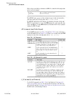
Page 633: ...y report of the last 255 records in the MIRRORED BITS communications buffer COM L A Appends a long report to the summary report of the last 255 records in the communications buffer for MIRRORED BITS c...

Page 634: ...MET RP Reset peak demand metering values MET T Display RTD metering data PING x x x x t Determine if Ethernet port is functioning or configured properly x x x x is the IP address and t is the PING in...

Page 635: ...d logic settings from Group m to Group n FIL WRITE filename Transfer settings file filename from the PC to the relay GRO n Modify active group setting L_D Load new firmware LOO Enables loopback testin...

Page 636: ...This page intentionally left blank...
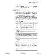
Page 637: ...y report of the last 255 records in the MIRRORED BITS communications buffer COM L A Appends a long report to the summary report of the last 255 records in the communications buffer for MIRRORED BITS c...

Page 638: ...MET RP Reset peak demand metering values MET T Display RTD metering data PING x x x x t Determine if Ethernet port is functioning or configured properly x x x x is the IP address and t is the PING in...

Page 639: ...d logic settings from Group m to Group n FIL WRITE filename Transfer settings file filename from the PC to the relay GRO n Modify active group setting L_D Load new firmware LOO Enables loopback testin...

Page 640: ...This page intentionally left blank...

Reviews: