H.4
SEL-751A Relay
Instruction Manual
Date Code 20100129
Synchrophasors
Settings for Synchrophasors
Settings for Synchrophasors
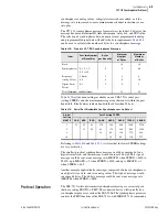
The phasor measurement unit (PMU) settings are listed in
. Modify
these settings when you want to use the C37.118 synchrophasor protocol.
The Global enable setting EPMU must be set to Y before the remaining
SEL-751A synchrophasor settings are available. No synchrophasor data
collection can take place when EPMU := N.
You must make the serial port settings in
to transmit data with a
synchrophasor protocol. It is possible to set EPMU := Y without using any
serial ports for synchrophasor protocols. For example, the serial port
MET PM
ASCII command can still be used.
Certain settings in
are hidden, depending on the status of other
settings. For example, if PHDATAI := NA, the ICOMP setting is hidden to
limit the number of settings for your synchrophasor application.
The Port settings for PROTO := PMU, shown in
, do not include the
settings DATABIT and PARITY; these two settings are internally fixed as
DATABIT := 8, PARITY := N (None). See
for
descriptions of these functions.
Table H.1
PMU Settings in the SEL-751A for C37.118 Protocol in Global
Settings
Setting
Description
Default
EPMU
Enable Synchronized Phasor Measurement
(Y, N)
N
a
a
Set EPMU := Y to access the remaining settings.
MRATE
Messages per Second {1, 2, 5, 10}
10
PMSTN
Station Name (16 characters)
SEL-751A FEEDER1
PMID
PMU Hardware ID (1–65534)
1
PHDATAV
Phasor Data Set, Voltages (V1, ALL, NA)
V1
VCOMP
Voltage Angle Comp Factor
(–179.99 to 180 deg)
0.00
PHDATAI
Phasor Data Set, Currents (I1, ALL, NA)
NA
ICOMP
Current Angle Comp Factor
(–179.99 to 180 deg)
0.00
NUMANA
Number of Analog Values (0–4)
0
NUMDSW
Number of 16-bit Digital Status Words (0, 1)
0
TREA1
Trigger Reason Bit 1 (SEL
OGIC
)
TRIP or ER
TREA2
Trigger Reason Bit 2 (SEL
OGIC
)
81D1T OR 81D2T OR
81D3T OR 81D4T
TREA3
Trigger Reason Bit 3 (SEL
OGIC
)
59P1T OR 59P2T
TREA4
Trigger Reason Bit 4 (SEL
OGIC
)
27P1T OR 27P2T
PMTRIG
Trigger (SEL
OGIC
)
TREA1 OR TREA2
OR TREA3 OR
TREA4
IRIGC
IRIG-B Control Bits Definition (NONE,
C37.118)
NONE
Summary of Contents for 751A
Page 1: ...20100129 SEL 751A Feeder Protection Relay Instruction Manual PM751A 01 NB...
Page 6: ...This page intentionally left blank...
Page 12: ...This page intentionally left blank...
Page 18: ...This page intentionally left blank...
Page 26: ...This page intentionally left blank...
Page 92: ...This page intentionally left blank...
Page 218: ...This page intentionally left blank...
Page 250: ...This page intentionally left blank...
Page 376: ...This page intentionally left blank...
Page 392: ...This page intentionally left blank...
Page 408: ...This page intentionally left blank...
Page 418: ...This page intentionally left blank...
Page 434: ...This page intentionally left blank...
Page 462: ...This page intentionally left blank...
Page 544: ...This page intentionally left blank...
Page 580: ...This page intentionally left blank...
Page 584: ...This page intentionally left blank...
Page 632: ...This page intentionally left blank...
Page 636: ...This page intentionally left blank...
Page 640: ...This page intentionally left blank...

