4.4
SEL-751A Relay
Instruction Manual
Date Code 20100129
Protection and Logic Functions
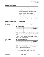
Group Settings (SET Command)
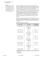
shows voltage settings for relay models with optional voltage inputs.
These settings configure the optional relay voltage inputs to correctly measure
and scale the voltage signals. Set the phase PT ratio (PTR) setting equal to the
VT ratio. The synchronism-check voltage input
VS
is an optional single phase-
neutral or phase-phase voltage input. Set the synchronism-check voltage input
PT ratio (PTRS) setting equal to the VT ratio of the
VS
input.
EXAMPLE 4.2
Phase VT Ratio Setting Calculations
Consider a 13.8 kV feeder application where 14400:120 V rated
voltage transformers (connected in open delta) are used.
Set PTR := 14400/120 := 120 and DELTA_Y := DELTA.
When phase-to-phase potentials are connected to the relay, set DELTA_Y to
DELTA. When phase-to-neutral potentials are connected to the relay, set
DELTA_Y to WYE.
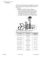
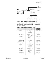
In applications where only a single voltage is available, set SINGLEV equal
to Y. As shown in
, the single voltage must be connected to the
A-phase input, but it may be an A-N or an A-B voltage. Be sure to set
DELTA_Y equal to WYE for an A-N input or DELTA_Y equal to DELTA for
an A-B input voltage.
When you set SINGLEV equal to Y, the relay performance changes in the
following ways:
➤
Voltage Elements.
When you use one phase-to-phase voltage,
the relay overvoltage and undervoltage elements use the
applied phase-to-phase voltage only. When you use one phase-
to-neutral voltage, the relay voltage elements use the applied
phase-to-neutral voltage only.
➤
Power Elements.
When you use one voltage, the relay assumes
that the system voltages are balanced in both magnitude and
phase angle to calculate apparent, real, and reactive power and
power factor.
➤
Metering.
When you use one voltage, the relay displays that
magnitude and phase angle. The relay displays zero for the
magnitudes of the unmeasured voltages. Balanced voltages are
assumed for power, power factor, VG, and 3V2 metering.
Relays that are not equipped with phase voltage inputs hide these settings and
disable voltage-based protection and metering functions.
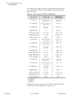
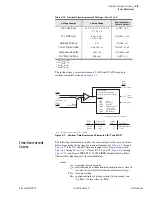
Table 4.3
Voltage Configuration Settings
Setting Prompt
Setting Range
Setting Name :=
Factory Default
PHASE PT RATIO
1.00–10000.00
PTR := 180
SYNCV PT RATIO
1.00–10000.00
PTRS :=180
XFMR CONNECTION
WYE, DELTA
DELTA_Y := DELTA
LINE VOLTAGE
100–250 V
a
a
The line voltage setting range is 100–440 if DELTA_Y := WYE.
VNOM := 120
SINGLE V INPUT
Y, N
SINGLEV := N
Summary of Contents for 751A
Page 1: ...20100129 SEL 751A Feeder Protection Relay Instruction Manual PM751A 01 NB...
Page 6: ...This page intentionally left blank...
Page 12: ...This page intentionally left blank...
Page 18: ...This page intentionally left blank...
Page 26: ...This page intentionally left blank...
Page 92: ...This page intentionally left blank...
Page 218: ...This page intentionally left blank...
Page 250: ...This page intentionally left blank...
Page 376: ...This page intentionally left blank...
Page 392: ...This page intentionally left blank...
Page 408: ...This page intentionally left blank...
Page 418: ...This page intentionally left blank...
Page 434: ...This page intentionally left blank...
Page 462: ...This page intentionally left blank...
Page 544: ...This page intentionally left blank...
Page 580: ...This page intentionally left blank...
Page 584: ...This page intentionally left blank...
Page 632: ...This page intentionally left blank...
Page 636: ...This page intentionally left blank...
Page 640: ...This page intentionally left blank...

