16
SEL Application Guide 2020-04
Date Code 20200326
C
ONSIDERATIONS
FOR
P
ILOT
P
ROTECTION
B
ETWEEN
D
ISSIMILAR
R
ELAYS
Different relays with different sensitivities used in pilot schemes can cause issues with coordina-
tion. See
for an example system. The relay installed on Breaker 3 is an SEL-400 series
relay and the relay installed on Breaker 4 is an SEL-300 series relay. When you are using two dis-
similar relays, there may be coordination problems because the relays may have different process-
ing speeds. Also, the SEL-421-3, SEL-421-5, and SEL-421-7 have high-speed distance elements
to reduce operating time. These features make SEL-400 series relays faster than SEL-300 series
relays, and this must be accounted for in the coordination time delays.
If a fault occurs on the line between Breakers 5 and 6 in a POTT scheme, Breaker 3 sends a PT sig-
nal to the relay at Breaker 4 (if the relay at Breaker 3 is set sensitively enough to detect the fault).
If the protection at Breaker 4 is not sensitive enough to detect this reverse fault and Breaker 4 uses
echo logic, as explained in [1], Breaker 4 echoes the received PT signal. The result is that
Breaker 3 trips for an out-of-section fault. This misoperation can be avoided with more sensitive
reverse-reaching protection elements at Breaker 4.
If the blocking relay is slow compared to the tripping relay, miscoordination can occur. To solve
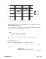
this problem, make sure Zone 3 always overreaches the remote Zone 2 by using
to set
Zone 3 of the local relay. Only apply this equation for two-terminal lines.
Equation 1
Now Zone 3 is set so that it overreaches Zone 2 of the remote relay with a margin of 25 percent.
also compensates for any differences in the CT and PT ratios at the local and remote
terminals. Perform this exercise at least twice at each end of the line to make sure that Zone 3 is
defined as explained previously. Doing this prevents tripping for an out-of-section fault.
For a reliable POTT scheme, the relays at each line terminal should have similar sensitivities. If the
sensitivities are not matched, a misoperation or failure to operate could occur. When coordinating
SEL-400 series relays with SEL-300 series relays, consult your fault study to ensure that each
relay has adequate operating quantities for all internal and external faults.
For a more detailed discussion of ground-relaying sensitivities, refer to [6] [7]. These papers iden-
tify relay sensitivity limits and fault resistance coverage for various fixed and settable directional
element limits. They also provide some useful tools for verifying relay settings in practice.
Figure 16
Example System Single-Line Diagram Showing Sensitivity Miscoordination
Zone 2
Zone 3
Zone 3
Zone 2
1
2
4
3
6
5
4
Bus A
Bus B
Z3
Local
Z2
Remote
PTR
CTR
------------
Remote
CTR
PTR
------------
Local
Z1MAG
Local
–
•
1.25
•
=


