18
SEL Application Guide 2020-04
Date Code 20200326
A
PPENDIX
A: D
ETERMINING
C
OORDINATION
T
IME
D
ELAY
This appendix shows example settings for the 21SD timer (Zone 2 Phase and Ground Coordination
Time Delay) and the 67SD timer (67G and 67Q Coordination Time Delay) when the SEL-421-5
and the SEL-311C-0 are used to set up a DCB scheme.
and assume that Relay 1 is an SEL-421-5 and that Relay 2 is an
SEL-311C-0, and that the relays are connected with a single-mode optical fiber for communica-
tions.
Recommendations for the 21SD Timer
The recommended setting for the 21SD timer is the sum of the following three times:
➤
Control input recognition time (including debounce timer)
➤
Remote Zone 3 distance protection maximum operating time
➤
Maximum communications channel time
21SD Calculation for the SEL-421-5
Control Input Recognition Time
shows the M
IRRORED
B
ITS
data delay times for different baud rates [4].
A data delay is the time between the assertion of the transmit bit in one device and the bit being
received and processed in the other device when the devices are connected back to back. The
SEL-400 series relays have a 1/8-cycle processing interval and most other SEL relays have 1/4-
cycle processing interval.The SEL-421-5 relay with a baud rate of 38400 has a typical data delay
of 8.3 ms if it is communicating with the SEL-311C-0, which has a processing interval of 1/4-
cycles. With this information, the data delay in cycles can be determined as shown:
where 60 is the conversion from seconds to cycles.
Maximum Communications Channel Time
The maximum communications channel time depends on the distance between the two relays that
are communicating with each other and the mode of communication (e.g., single mode fiber-optic,
multimode fiber-optic, serial cable, etc.).
For example, assume that the relays are 32.2 km apart and connected by an SEL-C809 9 µm
Single-Mode Fiber Cable. The typical communications delay for a single-mode fiber-optic cable is
5 µs per 1 km.
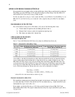
Table 17
M
IRRORED
B
ITS
Data Delay Times
Baud Rate
Typical Data Delay of 1/8-Cycle Processing
Interval Devices (Maximum)
Typical Data Delay of 1/4-Cycle Processing
Interval Devices (Maximum)
38400
4.2 ms (4.2 ms)
8.3 ms (8.3 ms)
19200
6.3 ms (6.3 ms)
10.5 ms (12.5 ms)
9600
8.3 ms (10.4 ms)
12.5 ms (12.5 ms)
4800
12.5 ms (18.7 ms)
16.7 ms (20.8 ms)
Data Delay
0.0083 s
=
Data Delay
60.0000 0.0083
0.5000 cycles
=
•
=


