background image

22

SEL Application Guide 2020-04

Date Code 20200326

Use 

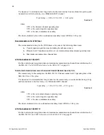
Equation 5

 to determine how long it takes for the remote relay distance element to pick up and 

transmit data to the local relay via a M

IRRORED

 B

ITS

 channel.


Equation 5


The final calculated value of the coordination time delay timer (21SD) is 1.40 cycles.

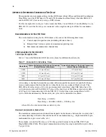
Recommendations for 67SD Timer

The recommended setting for the 67SD timer is the sum of the following three times: 

Control input recognition time (including the debounce timer)

Remote Level 3 nondirectional low-set overcurrent element maximum operating time

Maximum communications channel time

67SD Calculation for SEL-421-5

For the control input recognition time and maximum communication channel time calculations for 
the SEL-421-5, see 

21SD Calculation for the SEL-421-5

 on page 18.

Remote Level 3 Nondirectional Low-Set Overcurrent Element Maximum Operating Time

The remote relay in this example is the SEL-311C-0. The maximum Level 3 operating time of the 
SEL-311C-0 is 1.50 cycles.

Use 

Equation 6

 to determine how long it takes for the remote relay overcurrent element to pick up 

and transmit data to the local relay via a M

IRRORED

 B

ITS

 channel.


Equation 6


The final calculated value of coordination time delay timer (67SD) is 2.01 cycles.

67SD Calculation for SEL-311C-0

For the control input recognition time and maximum communication channel time calculations for 
the SEL-311C-0, see 

21SD Calculation for the SEL-311C-0

 on page 20.

where:

0.90 is the distance element operating time 
0.50 is the control input recognition time
0.01 is the data communications delay

Total delay

0.90 0.50 0.01

+

+

1.40 cycles

=

=

where:

1.50 is the overcurrent element operating time
0.50 is the control input recognition time
0.01 is the data communications delay

Total delay

1.50 0.50 0.01

2.01 cycles

=

+

+

=

Summary of Contents for SEL-300 Series

Page 1: ...ered in this applica tion guide is the SEL 421 5 Protection Automation and Control System The SEL 300 series relays covered in this application guide include the SEL 311C 1 Transmission Protection System the SEL 311L Line Current Differential Protection and Automation System and the SEL 321 1 Phase and Ground Distance Relay For the examples in this guide we use the SEL 421 5 to represent all the S...

Page 2: ...correct baud rate depends on the mode of communications between the two relays If a direct fiber optic cable is used industry practice is to use a higher baud rate Generally fiber is capable of operating at higher baud rates because it has a faster data transfer capability When you use other modes of communication lower baud rates should be considered based on the data trans fer capability of the ...

Page 3: ...ctions to devices that are not SEL 400 series relays f y 1 to 8 g To maintain security during a loss of communications in a POTT scheme you can set the default state of the permissive receive bit RMB1A to 0 thus RMB1FL 0 In a DCB scheme you can set the default state of the block bit RMB1A to 1 thus RMB1FL 1 Table 2 SEL 311C 1 Port 2 Settings For Communications Between SEL 421 5 and SEL 311C 1 Rela...

Page 4: ...he SEL 321 5 are limited to 9600 RTS_CTS Enable Hardware Handshaking N Not needed for relay to relay communications RBADPU MIRRORED BITS Receive Bad Pickup 60 default A channel error must last 60 seconds before RBADxc asserts CBADPU PPM MIRRORED BITS Channel Bad Pickup 1000 default CBAD asserts if the ratio of channel downtime to total channel time exceeds this value TX_ID MIRRORED BITS Transmit I...

Page 5: ...cks permission to the remote terminal For example referencing Figure 5 if a fault occurs at Point F1 the overreaching Zone 2 element at Relay 1 asserts while the reverse looking Zone 3 element remains deasserted This makes the out put of AND 1 shown in Figure 6 assert sending a permissive trip PT signal key to Relay 2 TAR ROKA Enter ROKA RBADA CBADA LBOKA ANOKA DOKA 1 0 0 0 0 0 0 0 Figure 2 Status...

Page 6: ... Zone 3 element asserts This means that AND 4 does not become true Therefore a key is not sent to Relay 1 which prevents a high speed trip At Relay 2 even though a key has been received on the bottom input of AND 3 the top input of AND 3 deasserts preventing a high speed trip NOTE This section provides an overview of POTT schemes For a more in depth discussion refer to 1 POTT SETUP To setup a POTT...

Page 7: ...ng a current reversal EBLKD Echo Block Time Delay 10 default Prevents the echoing of a received PT for a settable delay after the dropout of the local permissive elements ETDPU Echo Time Delay Pickup 2 default Sets a minimum time requirement for the received PT before echo begins EDURD Echo Duration Time Delay 4 default Limits the echo duration to prevent channel lockup EWFC Weak Infeed Enable N d...

Page 8: ... 421 5 and SEL 311C 1 program PT1 to RMB1A In the SEL 321 1 program RMB1 to PT A tripping output must be assigned to trip the respective circuit breaker of each relay In the SEL 421 5 set OUT201 to TRIP in the SEL 311C 1 set OUT101 to TRIP and in the SEL 321 1 set OUT1 to 3PT as shown in Figure 9 and Figure 10 You should wire a breaker contact status to each relay In the SEL 421 5 wire 52A to IN20...

Page 9: ...e mho phase and mho ground distance elements Elements that allow high speed communications assisted tripping TMB1 Transmit Mirrored Bit 1 KEY Send a PT to the remote end RMB1b b Because PROTOCOL MB set RMB1 in Global settings Receive Mirrored Bit 1 PT Receive a PT from the remote end OUT1 Output Contact Logic OUT1 3PT Trip the output to the circuit breaker IN1 Input Contact 1 Assignment 52A1 Assig...

Page 10: ...gnal to Relay 2 The assertion of Zone 2 starts TIMER 1 see Figure 11 If Zone 2 asserts for longer than the programmed timer delay coordination time delay CTD in TIMER 1 the top input of AND 1 becomes true If the top input of AND 1 is true and Relay 1 has not received a block from the remote end Relay 1 issues a trip At Relay 2 Zone 2 asserts and Zone 3 remains deasserted Figure 9 Simplified Wiring...

Page 11: ... of DCB schemes For a more in depth discussion refer to 2 DCB SETUP To setup a DCB scheme in the SEL 421 5 SEL 311L or SEL 321 1 relays you must enable the logic in the relays The settings in the relays are similar Table 11 Table 12 and Table 13 provide a summary of how to set up the DCB logic in the SEL 421 5 SEL 311C 1 and SEL 321 1 respec tively These settings only apply to directional starting...

Page 12: ... Setting Description Setting Value Description ECOMM Communication Assisted Trip Scheme DCB Enables the DCB logic in the SEL 311C 1 Z3XPU Zone 3 Reverse Pickup Time Delay 1 default Current reversal guard pickup timer Z3XD Zone 3 Pickup Extension Time Delay 6 Prevents a DCB scheme misoperation during current reversal this also matches the SEL 421 5 for better coordination BTXD Block Trip Receive Ex...

Page 13: ...lds for the SEL 300 series relays Each relay must be able to transmit a block signal In the SEL 421 5 and SEL 311C 1 send the block via TMB1A and in the SEL 321 1 send it via TMB1 The relays must be programmed to map the BLOCK element from the remote end into the DCB logic Map the BLOCK element to the received Mirrored Bit In the SEL 421 5 and SEL 311C 1 program BT to RMB1A and in the SEL 321 1 pr...

Page 14: ...ock signal to the remote end BT Block Trip Equation RMB1A Receive a block signal from the remote end OUT101 Output Contact 101 Equation TRIP Trip the output to the circuit breaker 52A Circuit Breaker Status Equation IN101 Assign to the circuit breaker 52a status ORDERb b Match the ORDER setting value in the SEL 421 5 to the ORDER setting value in the SEL 311C 1 Ground Directional Priority b Set to...

Page 15: ... and SEL 321 1 Relays Zone 3 TRIP SEL 421 5 TRCOMM BT RMB1A DSTRT TMB1A Zone 3 3PT SEL 321 1 MTCS BT RMB1 START TMB1 52A SEL 311C 1 Partial A01 A17 OUT101 IN101 A02 A18 52A 52TC Circuit Breaker Partial 52A SEL 421 5 Partial B01 B33 OUT201 IN201 B02 B34 52A 52TC Circuit Breaker Partial 52A SEL 321 1 Partial 218 201 OUT1 IN1 217 202 52A 52TC Circuit Breaker Partial 52A SEL 421 5 Partial B01 B33 OUT2...

Page 16: ...ocking relay is slow compared to the tripping relay miscoordination can occur To solve this problem make sure Zone 3 always overreaches the remote Zone 2 by using Equation 1 to set Zone 3 of the local relay Only apply this equation for two terminal lines Equation 1 Now Zone 3 is set so that it overreaches Zone 2 of the remote relay with a margin of 25 percent Equation 1 also compensates for any di...

Page 17: ... both line terminals match Use the same protective elements at each line terminal whenever possible and set the reverse reaching elements at a greater sensitivity than the remote overreaching elements That the directional elements and pickup settings at each line terminal have sufficient operating quantities to detect both internal and external faults If you cannot follow the previous consideratio...

Page 18: ...es are connected back to back The SEL 400 series relays have a 1 8 cycle processing interval and most other SEL relays have 1 4 cycle processing interval The SEL 421 5 relay with a baud rate of 38400 has a typical data delay of 8 3 ms if it is communicating with the SEL 311C 0 which has a processing interval of 1 4 cycles With this information the data delay in cycles can be determined as shown wh...

Page 19: ...maximum operating times Figure 17 and Figure 18 show the operating curves for the SEL 311C 0 If you use any relay other than the SEL 311C 0 refer to the respective instruction manual for the operating curves Distance 32 20000 km Delay Communications 32 20000 km 5 00000 s km 0 00016 s Delay 60 00000 0 00016 s 0 01000 cycles Figure 17 Operating Time Curve of the SEL 311C 0 for a Phase to Phase Fault...

Page 20: ...S data delay times for different baud rates 4 The SEL 311C 0 relay with a baud rate of 38400 has a typical data delay of 8 3 ms because its pro cessing interval is 1 4 cycles With this information use Equation 4 to calculate the data delay in cycles Equation 4 Figure 18 Operating Time Curve of the SEL 311C 0 for a Phase to Ground Fault SIR 0 1 SIR 1 0 SIR 10 0 SIR 30 0 0 10 20 90 30 40 50 60 70 80...

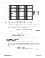
Page 21: ...e 3 distance protection maximum operating times Figure 19 and Figure 20 show the operating curves for high speed distance elements Consider the worst case operation and assume SIR 1 The maximum operating time of a distance element is about 0 90 cycles Figure 19 Operating Time Curve of the SEL 421 5 for a Phase to Phase Fault Figure 20 Operating Time Curve of the SEL 421 5 for a Phase to Ground Fau...

Page 22: ...Remote Level 3 Nondirectional Low Set Overcurrent Element Maximum Operating Time The remote relay in this example is the SEL 311C 0 The maximum Level 3 operating time of the SEL 311C 0 is 1 50 cycles Use Equation 6 to determine how long it takes for the remote relay overcurrent element to pick up and transmit data to the local relay via a MIRRORED BITS channel Equation 6 The final calculated value...

Page 23: ...odero Implementing MIRRORED BITS Technology Over Various Com munications Media SEL Application Guide AG2001 12 2007 Available selinc com 4 M Diehl and A Dulmage Understanding and Effectively Using the SEL MIRRORED BITS Protocol Application Guide AG2018 24 2019 Available selinc com 5 R McDaniel Applying the SEL 421 Relay to Permissive Overreaching Transfer Trip Schemes SEL Application Guide AG2010 ...

Page 24: ...EL products appearing in this document may be covered by U S and Foreign patents 2350 NE Hopkins Court Pullman WA 99163 5603 U S A Tel 1 509 332 1890 Fax 1 509 332 7990 selinc com info selinc com TECHNICAL SUPPORT We appreciate your interest in SEL products and services If you have questions or comments please contact us at Schweitzer Engineering Laboratories Inc 2350 NE Hopkins Court Pullman WA 9...

Reviews: