U.2.45
Date Code 20020501
User’s Guide
SEL-421/SEL-421-1 Relay
Installation
Connection
In addition, the rear panel features a PORT 5 for an optional communications
card. For additional information about communications topologies and
standard protocols that are available in the SEL-421 Relay, see
SEL-2030 Applications in the Applications Handbook
Network Communication in the Application Handbook
, the
3.0 Communications in the Reference Manual
, and the
Communications in the Reference Manual
.
Serial Ports
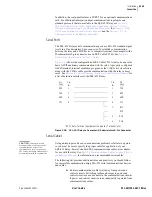
The SEL-421 Relay serial communications ports use EIA-232 standard signal
levels in a D-subminiature 9-pin connector. To establish communication
between the relay and a DTE device (a computer terminal, for example) with a
D-subminiature 9-pin connector, use an SEL Cable C234A. See
Basic Relay Operations in the User’s Guide
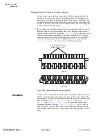
shows the configuration of SEL Cable C234A that you can use for
basic ASCII and binary communication with the relay. A properly configured
ASCII terminal, terminal emulation program, or the
AC
SEL
ERATOR
software
along with the C234A cable provide communication with the relay in most
cases. See
Section 4: Communications Interfaces in the Reference Manual
for
a list of hardware interfaces to the SEL-421 Relay.
Figure 2.30
SEL-421 Relay to Computer—D-Subminiature 9-Pin Connector.
Serial Cables
CAUTION:
Severe power and
ground problems can occur on the
communications ports of this
equipment as a result of using non-
SEL cables. Never use Standard null-
modem cables with this equipment.
Using an improper cable can cause numerous problems or failure to operate,
so you must be sure to specify the proper cable for application of your
SEL-421 Relay. Several standard SEL communications cables are available
for use with the relay. See
EIA-232 Communications Cables on page R.4.4 in
for information on recommended serial cables.
The following list provides additional rules and practices you should follow
for successful communication using EIA-232 serial communications devices
and cables:
➤
Route communications cables well away from power and
control circuits. Switching spikes and surges in power and
control circuits can cause noise in the communications circuits
if power and control circuits are not adequately separated from
communications cables.
*DTE = Data Terminal Equipment (Computer, Terminal, etc.)
2
3
3
5
8
2
5
8
7
RXD
TXD
TXD
RXD
GND
GND
CTS
CTS
RTS
DCD
DTR
DSR
1
4
6
Pin
Func.
Pin
Func.
Pin
#
Pin
#
Summary of Contents for SEL-421
Page 8: ...This page intentionally left blank ...
Page 30: ...This page intentionally left blank ...
Page 110: ...This page intentionally left blank ...
Page 204: ...This page intentionally left blank ...
Page 284: ...This page intentionally left blank ...


