U.4.72
SEL-421/SEL-421-1 Relay
User’s Guide
Date Code 20020501
Basic Relay Operations
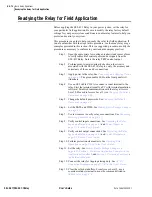
Readying the Relay for Field Application
Readying the Relay for Field Application
Before applying the SEL-421 Relay in your power system, set the relay for
your particular field application. Be sure to modify the relay factory default
settings for your power system conditions to enable relay features to help you
protect and control your system.
This procedure is a guide to help you ready the relay for field application. If
you are unfamiliar with the steps in this procedure, see the many relay usage
examples presented in this section. This is a suggested procedure; modify the
procedure as necessary to conform to your standard company practices.
Step 1. Open the appropriate low-voltage breaker(s) and remove fuses
to verify removal of control power and ac signals from the
SEL-421 Relay. Isolate the relay TRIP control output.
Step 2. Perform point-to-point continuity checks on the circuits
associated with the SEL-421 Relay to verify the accuracy and
correctness of the ac and dc connections.
Step 3. Apply power to the relay. See
. The green enable LED on the front panel will
illuminate.
Step 4. Use an SEL Cable C234A to connect a serial terminal to the
relay. Start the terminal (usually a PC with terminal emulation
software). Establish communication with the relay at Access
Level 0. Proceed to Access Level 2 (see
Step 5. Change the default passwords. See
Step 6. Set the DATE and TIME. See
Making Simple Settings Changes
Step 7. Use test sources to verify relay ac connections. See
Metering Quantities on page 4.31
.
Step 8. Verify control input connections. See
Inputs and Outputs on page 4.52
and
page U.2.6 in the User’s Guide
Step 9. Verify control output connections. See
Inputs and Outputs on page 4.52
and
page U.2.6 in the User’s Guide
Step 10. Perform protection element tests. See
Operation on page U.6.24 in the User’s Guide
.
Step 11. Set the relay. See
Making Simple Settings Changes on
,
Section 1: Protection Application Examples in the
, and
Section 1: Protection Functions in
Step 12. Connect the relay for tripping/closing duty. See
Connection Diagrams on page U.2.47 in the User’s Guide
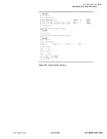
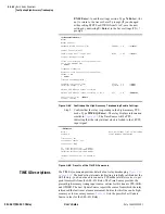
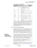
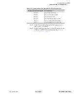
Step 13. Clear the relay data buffers. From Access Level 2, use a
communications terminal to issue the commands listed in
Summary of Contents for SEL-421
Page 8: ...This page intentionally left blank ...
Page 30: ...This page intentionally left blank ...
Page 110: ...This page intentionally left blank ...
Page 204: ...This page intentionally left blank ...
Page 284: ...This page intentionally left blank ...


