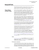
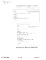
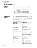
background image

U.6.35

Date Code 20020501

User’s Guide

SEL-421/SEL-421-1 Relay

Testing and Troubleshooting

Checking Relay Operation

level passwords and enter higher relay access levels. You should be familiar 
with the 

AC

SEL

ERATOR

 software. See 

Section 3: PC Software in the User’s 

Guide

.

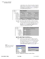
Step 1. Configure the relay. Begin the 

AC

SEL

ERATOR

 software and 

read the present configuration in the SEL-421 Relay. On the 
Settings menu, click Read. The relay sends all settings and 
configuration data to the 

AC

SEL

ERATOR

 software. Expand the 

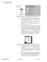
Group 1 settings and click the Relay Configuration branch of 
the Settings tree view as shown in 

Figure 6.23 on page 6.29

Confirm that E21P is 2 or greater (the factory default is 3).

 Disable element supervisory conditions. On the Relay 
Configuration dialog box, confirm that ELOAD and ELOP are 
set to N. See 

Mho Phase Distance Elements on page R.1.55 in 

the Reference Manual

 to determine the supervisory conditions 

for the MBC2 element. Confirm that Directional Element 
Control E32 is AUTO.

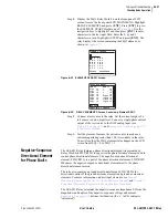
Defeat the pole-open logic. Click the + button next to Breaker 
Monitor to expand the Breaker Monitor branch of the Settings 
tree view (see 

Figure 6.24 on page 6.30

). Click Breaker 1. You 

will see the Breaker 1 dialog box similar to 

Figure 6.24

. Enter 

1

 in the text boxes for 52AA1 A-Phase N/O Contact Input–

BK1, 52AB1 B-Phase N/O Contact Input–BK1, and 52AC1 
C-Phase N/O Contact Input–BK1. The text boxes in 

Figure 6.24 on page 6.30

 appear if Breaker Monitor setting 

BK1TYP := 1. If BK1TYP := 3, enter 1 in the 52AA1 N/O 
Contact Input–BK1 text box (the other circuit breaker input 
boxes are dimmed.)

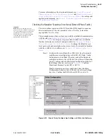
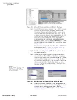
Step 2. Set test values in the relay. Expand the Group 1 settings as 

shown in 

Figure 6.25 on page 6.30

 and select the Line 

Configuration button. You will see the Line Configuration 
dialog box of 

Figure 6.25

. Confirm the default settings of 

Z1MAG at 7.80 and Z1ANG at 84.00. Click the + mark next to 
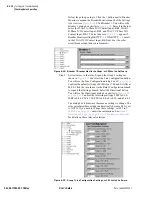
the Relay Configuration branch to expand that Settings branch. 
Select the Directional button. You will see the Directional 
dialog box similar to 

Figure 6.26 on page 6.31

. Confirm the 

settings 50FP to 0.60, 50RP to 0.40, Z2F to 3.90, Z2R to 4.00, 
a2 to 0.10, and k2 to 0.2. The relay calculates these settings 
automatically because E32 is AUTO. There are no settings to 
change; the dialog box is dim. 

Table 6.8 on page 6.31

 shows 

the calculations. See 

Ground Directional Element on 

page R.1.21 in the Reference Manual

 for details on these relay 

calculations.

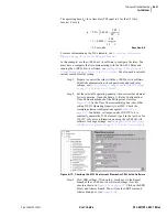
Step 3. Set the phase distance element reach. Select the Phase Distance 

button of the 

AC

SEL

ERATOR

 software Settings tree view. You 

will see the Phase Distance Elements dialog box similar to 

Figure 6.30 on page 6.36

. Confirm the default settings of Z1P 

at 6.24 and Z2P at 9.36.

Summary of Contents for SEL-421

Page 1: ...Schweitzer Engineering Laboratories 2350 NE Hopkins Court Pullman WA USA 99163 5603 Tel 509 332 1890 FAX 509 332 7990 SEL 421 Relay SEL 421 1 Relay Protection Automation Control User s Guide ...

Page 2: ...asser des piles usagées suivant les instructions du fabricant DANGER Débrancher tous les raccordements externes avant d ouvrir cet appareil Tout contact avec des tensions ou courants internes à l appareil peut causer un choc électrique pouvant entraîner des blessures ou la mort DANGER Tout contact avec les bornes de l appareil peut causer un choc électrique pouvant entraîner des blessuers ou la mo...

Page 3: ...s U 2 47 Section 3 PC Software Installing the Computer Software U 3 2 Communications Setup U 3 4 Settings Database Management and Drivers U 3 6 Create and Manage Relay Settings U 3 9 Expression Builder U 3 13 Analyze Events U 3 15 HMI Meter and Control U 3 19 Section 4 Basic Relay Operations Inspecting a New Relay U 4 2 Connecting and Applying Power U 4 4 Establishing Communication U 4 5 Changing ...

Page 4: ...ing Example A 1 20 345 kV Tapped Overhead Transmission Line Example A 1 53 EHV Parallel 230 kV Underground Cables Example A 1 86 Out of Step Logic Application Examples A 1 118 Auto Reclose Example A 1 136 Auto Reclose and Synchronism Check Example A 1 140 Circuit Breaker Failure Application Examples A 1 151 Section 2 Monitoring and Metering Circuit Breaker Monitor A 2 2 Station DC Battery System M...

Page 5: ...hase and Negative Sequence Directional Elements R 1 33 Directionality R 1 35 CVT Transient Detection R 1 36 Series Compensation Line Logic R 1 38 Load Encroachment Logic R 1 39 OOS Logic R 1 41 Mho Ground Distance Elements R 1 46 Quadrilateral Ground Distance Elements R 1 51 Mho Phase Distance Elements R 1 55 Zone Time Delay R 1 59 Instantaneous Line Overcurrent Elements R 1 62 Inverse Time Overcu...

Page 6: ... Active When Setting PROTO SEL R 5 5 Virtual File Interface R 5 14 SEL MIRRORED BITS Communications R 5 18 SEL Distributed Port Switch Protocol LMD R 5 25 Section 6 DNP 3 0 Communications Introduction to DNP 3 0 R 6 2 DNP 3 0 in the SEL 421 Relay R 6 6 DNP 3 0 Documentation R 6 13 Application Example R 6 29 Section 7 UCA2 Communications Introduction to UCA2 R 7 2 UCA2 in the SEL 421 Relay R 7 5 GO...

Page 7: ...lay Table of Contents Appendix C GOMSFE Tables Introduction R C 1 GOMSFE Tables R C 2 SEL 421 Relay Domains R C 3 SEL 421 Relay Domain LN0 R C 4 SEL 421 Relay Virtual Device Domain R C 9 Special Translation Rules R C 17 Glossary GL 1 Index IN 1 ...

Page 8: ...This page intentionally left blank ...

Page 9: ... Prompts U 4 21 Table 4 8 Time Source Automatic Switching Enable Settings U 4 66 Table 4 9 Date Time Last Update Sources U 4 69 Table 4 10 Communications Port Commands That Clear Relay Buffers U 4 73 Section 5 Front Panel Operations Table 5 1 Front Panel Inactivity Time Out Setting U 5 3 Table 5 2 Metering Screens Enable Settings U 5 4 Table 5 3 Display Point Settings U 5 7 Table 5 4 Local Bit Con...

Page 10: ... Table 1 26 XAG Measurement for Remote AG Fault k01 0 374 39 2 sheath and ground return path A 1 98 Table 1 27 XAG Measurement for Remote AG Fault k01 0 385 46 7 sheath return path A 1 99 Table 1 28 XAG Measurement for Remote AG Fault k0 6 105 44 5 ground return path A 1 99 Table 1 29 Options for Enabling Pole Open Logic A 1 108 Table 1 30 Setting TULO Unlatch Trip Options A 1 111 Table 1 31 Gener...

Page 11: ...Report Nonvolatile Storage Capability A 3 7 Table 3 3 EVE Command A 3 13 Table 3 4 EVE Command Examples A 3 14 Table 3 5 Event Report Metered Analog Quantities A 3 15 Table 3 6 Event Types A 3 29 Table 3 7 SUM Command A 3 30 Table 3 8 HIS Command A 3 32 Table 3 9 SER Commands A 3 35 Section 4 Time Synchronized Measurements Table 4 1 SEL 421 Relay Voltage and Current Measurement A 4 8 Section 5 Sub...

Page 12: ...d Negative Sequence Directional Elements Relay Word Bits R 1 33 Table 1 28 Zone Directional Settings R 1 35 Table 1 29 CVT Transient Detection Logic Setting R 1 36 Table 1 30 CVT Transient Detection Logic Relay Word Bit R 1 36 Table 1 31 Series Compensation Line Logic Relay Settings R 1 38 Table 1 32 Load Encroachment Logic Relay Settings R 1 40 Table 1 33 Load Encroachment Logic Relay Word Bits R...

Page 13: ... State R 2 21 Table 2 15 Example Three Three Pole Cycle State R 2 21 Table 2 16 Example Three Lockout State BK1 R 2 22 Table 2 17 Leader Follower Selection R 2 22 Table 2 18 Two Circuit Breakers Circuit Breaker BK1 Out of Service R 2 23 Table 2 19 Two Circuit Breaker Three Pole Reclose Initial Settings R 2 23 Table 2 20 Two Circuit Breaker Single Pole Reclose Initial Settings R 2 24 Table 2 21 Cir...

Page 14: ...1 Table 5 8 Analog Quantities Included in the Synchrophasor Fast Message R 5 11 Table 5 9 Fast Message Command Function Codes for Synchrophasor Fast Write R 5 12 Table 5 10 Commands in Recommended Sequence for Automatic Configuration R 5 13 Table 5 11 Virtual File Structure R 5 14 Table 5 12 Settings Directory Files R 5 16 Table 5 13 REPORTS Directory Files R 5 16 Table 5 14 EVENTS Directory Files...

Page 15: ...rence Table 8 1 2AC Command R 8 2 Table 8 2 AAC Command R 8 2 Table 8 3 ACC Command R 8 2 Table 8 4 BAC Command R 8 2 Table 8 5 BNA Command R 8 2 Table 8 6 BRE n Command R 8 3 Table 8 7 BRE n C and BRE n R Commands R 8 3 Table 8 8 BRE C A and BRE R A Commands R 8 3 Table 8 9 BRE n H Command R 8 3 Table 8 10 BRE n P Command R 8 4 Table 8 11 CAS Command R 8 4 Table 8 12 CBR Command R 8 4 Table 8 13 ...

Page 16: ... 63 ID Command R 8 24 Table 8 64 IRIG Command R 8 25 Table 8 65 LOOP Command R 8 26 Table 8 66 LOOP DATA Command R 8 26 Table 8 67 LOOP R Command R 8 27 Table 8 68 MAP 1 Command R 8 27 Table 8 69 MAP 1 Region Command R 8 27 Table 8 70 MET Command R 8 28 Table 8 71 MET AMV Command R 8 28 Table 8 72 MET ANA Command R 8 29 Table 8 73 MET BAT Command R 8 29 Table 8 74 MET D Command R 8 29 Table 8 75 M...

Page 17: ... 47 Table 8 122 SUM Command R 8 47 Table 8 123 SUM ACK Command R 8 47 Table 8 124 SUM N Command R 8 48 Table 8 125 TAR Command R 8 48 Table 8 126 TAR ALL Command R 8 48 Table 8 127 TAR R Command R 8 49 Table 8 128 TAR X Command R 8 49 Table 8 129 TEST DB Command R 8 50 Table 8 130 TEST DB OFF Command R 8 50 Table 8 131 TEST DNP Command R 8 50 Table 8 132 TEST DNP Command R 8 51 Table 8 133 TEST FM...

Page 18: ...round Distance Element Time Delay R 9 15 Table 9 36 Distance Element Common Time Delay R 9 16 Table 9 37 Switch Onto Fault Scheme R 9 16 Table 9 38 Out of Step Tripping Blocking R 9 16 Table 9 39 Load Encroachment R 9 17 Table 9 40 Phase Instantaneous Overcurrent Pickup R 9 18 Table 9 41 Phase Definite Time Overcurrent Time Delay R 9 18 Table 9 42 Phase Instantaneous Definite Time Overcurrent Torq...

Page 19: ...s R 9 41 Table 9 94 Telnet Settings R 9 41 Table 9 95 Network Host Name R 9 42 Table 9 96 UCA Settings R 9 42 Table 9 97 DNP 3 0 Settings Categories R 9 43 Table 9 98 DNP 3 0 Object Default Map Enables R 9 43 Table 9 99 Binary Input Map R 9 43 Table 9 100 Binary Output Map R 9 43 Table 9 101 Counter Map R 9 43 Table 9 102 Analog Input Map R 9 44 Table 9 103 Analog Output Map R 9 44 Appendix A Rela...

Page 20: ...gic Bits R A 66 Table A 43 Relay Word Bits MIRRORED BITS R A 67 Table A 44 Relay Word Bits Test Bits R A 68 Table A 45 Relay Word Bits Communications Card Input Points R A 69 Table A 46 Relay Word Bits Communications Card Output Points R A 70 Table A 47 Relay Word Bits Communications Card Status Points R A 71 Table A 48 Relay Word Bits Fast SER Enable Bits R A 72 Table A 49 Relay Word Bits Source ...

Page 21: ...d Breaker Jumpers U 2 19 Figure 2 15 Major Component Locations on the SEL 421 Relay INT1 I O Board U 2 22 Figure 2 16 Major Component Locations on the SEL 421 Relay INT5 I O Board U 2 23 Figure 2 17 Major Component Locations on the SEL 421 Relay INT6 I O Board U 2 24 Figure 2 18 Blank Slide In Label Set and Label Removal Tool U 2 26 Figure 2 19 SEL 421 Relay Chassis Dimensions U 2 32 Figure 2 20 3...

Page 22: ...ccess Level Structure U 4 8 Figure 4 6 Default Passwords U 4 11 Figure 4 7 Relay Status U 4 12 Figure 4 8 ACSELERATOR Software Port Parameters and Password Entry U 4 13 Figure 4 9 Retrieving Relay Status ACSELERATOR Software U 4 13 Figure 4 10 Checking Relay Status Front Panel LCD U 4 14 Figure 4 11 Relay Settings Structure Overview U 4 16 Figure 4 12 Components of SET Commands U 4 18 Figure 4 13 ...

Page 23: ...P in the ACSELERATOR Software U 4 64 Figure 4 59 Setting 52AA1 in the ACSELERATOR Software U 4 64 Figure 4 60 Uploading Global and Breaker Monitor Settings to the SEL 421 Relay U 4 65 Figure 4 61 TIME BNC Jacks U 4 67 Figure 4 62 Confirming the High Accuracy Timekeeping Enable Settings U 4 68 Figure 4 63 Results of the TIME Q Command U 4 68 Figure 4 64 Programming a PSV in the ACSELERATOR Software...

Page 24: ...ure 6 10 Uploading Front Panel Settings to the SEL 421 Relay U 6 18 Figure 6 11 Setting Main Board Outputs ACSELERATOR Software U 6 19 Figure 6 12 Uploading Output Settings to the SEL 421 Relay U 6 19 Figure 6 13 Checking the 51S1 Overcurrent Element ACSELERATOR Software U 6 21 Figure 6 14 Setting SER Points and Aliases ACSELERATOR Software U 6 22 Figure 6 15 Uploading Group 1 and Report Settings ...

Page 25: ... 1 26 Negative Sequence Fault Current Distribution External Ground Fault A 1 103 Figure 1 27 Reverse Unbalanced Fault on Cable Circuit Shunt Admittance A 1 107 Figure 1 28 500 kV Power System A 1 118 Figure 1 29 OOS Characteristic Settings Parameters A 1 120 Figure 1 30 Calculating Setting R1R7 A 1 122 Figure 1 31 Swing Trajectory to Determine the OSBD Setting A 1 123 Figure 1 32 Inner Blinders A ...

Page 26: ... Digital Section of the Event Report A 3 20 Figure 3 10 Sample Digital Portion of the Event Report A 3 21 Figure 3 11 Summary Section of the Event Report A 3 22 Figure 3 12 Settings Section of the Event Report A 3 23 Figure 3 13 Sample Compressed ASCII Event Report A 3 27 Figure 3 14 Sample Event Summary Report A 3 28 Figure 3 15 Sample Compressed ASCII Summary A 3 31 Figure 3 16 Sample Event Hist...

Page 27: ... 32Q and 32QG Enable Logic Diagram R 1 25 Figure 1 13 32V and 32I Enable Logic Diagram R 1 25 Figure 1 14 Best Choice Ground Directional Logic R 1 27 Figure 1 15 Negative Sequence Voltage Polarized Directional Element Logic R 1 28 Figure 1 16 Zero Sequence Voltage Polarized Directional Element Logic R 1 28 Figure 1 17 Zero Sequence Current Polarized Directional Element Logic R 1 29 Figure 1 18 Gro...

Page 28: ...7 Current Supervised Three Pole Retrip Logic R 1 115 Figure 1 68 Current Supervised Single Pole Retrip Logic R 1 115 Figure 1 69 No Current Residual Current Circuit Breaker Failure Protection Logic Diagram R 1 116 Figure 1 70 Circuit Breaker Failure Seal In Logic Diagram R 1 121 Figure 1 71 Failure to Interrupt Load Current Logic Diagram R 1 121 Figure 1 72 Flashover Protection Logic Diagram R 1 1...

Page 29: ... Pickup and No Dropout Timing Diagram R 3 17 Figure 3 4 Conditioning Timer With Pickup Not Satisfied Timing Diagram R 3 17 Figure 3 5 Conditioning Timer With Dropout and No Pickup Timing Diagram R 3 18 Figure 3 6 Conditioning Timer With Pickup and Dropout Timing Diagram R 3 18 Figure 3 7 Conditioning Timer Timing Diagram for Example 3 7 R 3 19 Figure 3 8 Conditioning Timer Timing Diagram R 3 20 Fi...

Page 30: ...This page intentionally left blank ...
Page 31: ... 6 8 U 6 28 Equation 6 9 U 6 33 Equation 6 10 U 6 33 Equation 6 11 U 6 33 Equation 6 12 U 6 33 Equation 6 13 U 6 34 Equation 6 14 U 6 34 Appendix A Firmware Versions Applications Handbook Section 1 Protection Application Examples Equation 1 1 A 1 3 Equation 1 2 A 1 3 Equation 1 3 A 1 6 Equation 1 4 A 1 9 Equation 1 5 A 1 11 Equation 1 6 A 1 21 Equation 1 7 A 1 21 Equation 1 8 A 1 25 Equation 1 9 A...

Page 32: ...3 Equation 1 43 A 1 73 Equation 1 44 A 1 73 Equation 1 45 A 1 73 Equation 1 46 A 1 74 Equation 1 47 A 1 75 Equation 1 48 A 1 75 Equation 1 49 A 1 75 Equation 1 50 A 1 75 Equation 1 51 A 1 87 Equation 1 52 A 1 87 Equation 1 53 A 1 90 Equation 1 54 A 1 94 Equation 1 55 A 1 94 Equation 1 56 A 1 94 Equation 1 57 A 1 95 Equation 1 58 A 1 95 Equation 1 59 A 1 95 Equation 1 60 A 1 97 Equation 1 61 A 1 98...

Page 33: ...4 A 2 15 Equation 2 5 A 2 25 Equation 2 6 A 2 25 Equation 2 7 A 2 33 Section 3 Analyzing Data Equation 3 1 A 3 17 Equation 3 2 A 3 18 Equation 3 3 A 3 19 Equation 3 4 A 3 19 Equation 3 5 A 3 19 Section 4 Time Synchronized Measurements Equation 4 1 A 4 8 Section 5 Substation Automatic Restoration Section 6 SEL 2030 Applications Section 7 Direct Network Communication Reference Manual Section 1 Prote...

Page 34: ...tion 1 29 R 1 73 Equation 1 30 R 1 73 Equation 1 31 R 1 73 Equation 1 32 R 1 73 Equation 1 33 R 1 73 Equation 1 34 R 1 73 Equation 1 35 R 1 117 Section 2 Auto Reclose and Synchronism Check Equation 2 1 R 2 42 Equation 2 2 R 2 47 Equation 2 3 R 2 55 Section 3 SELOGIC Control Equation Programming Section 4 Communications Interfaces Section 5 SEL Communications Protocols Section 6 DNP 3 0 Communicati...

Page 35: ...ternal Trip Initiation A 2 8 Example 2 4 Using a Control Input to Capture External and Internal Trip Commands A 2 8 Example 2 5 Mechanical Operating Time Settings A 2 10 Example 2 6 Electrical Operating Time Settings A 2 12 Example 2 7 Pole Scatter Settings A 2 13 Example 2 8 Pole Discrepancy Alarm for Circuit Breaker 1 No Other Circuit Breaker Monitor Functions A 2 15 Example 2 9 Inactivity Time ...

Page 36: ...peration R 3 28 Example 3 12 Using Parentheses in Math Equations R 3 29 Example 3 13 Using Arithmetic Operations R 3 30 Example 3 14 Using the SQRT Operator R 3 31 Example 3 15 Using the LN EXP and LOG Operators R 3 31 Example 3 16 Using the SIN and COS Operators R 3 32 Example 3 17 Using the ASIN and ACOS Operators R 3 32 Example 3 18 Using the ABS Operator R 3 32 Example 3 19 Using the CEIL Oper...

Page 37: ...ntities for use in SELOGIC control equations Terminal W and X current magnitudes Terminal Y and Z voltage magnitudes Instantaneous sequence quantities Contact inputs Modified CHI output for SEL 2030 compatibility 20020108 SEL 421 1 Relay introduction Configurable front panel labels I and V Source Selection settings clarifications Preface Added Notes explanation User s Guide Section 1 Introduction ...

Page 38: ...dded Notes to flag the differences in the SEL 421 1 Relay Included more explanation for settings ALTI and ALTV in Current and Voltage Source Selection on page R1 2 Corrected setting ORDER text in ORDER on page R1 24 Supplemented Series Compensation Line Logic on page R1 38 material Reference Manual Section 3 SELOGIC Control Equation Programming Added Notes to flag the differences in the SEL 421 1 ...

Page 39: ...pplications Included are detailed technical descriptions of the relay and application examples While this manual gives reasonable examples and illustrations of relay uses you must exercise sound judgment at all times when applying the SEL 421 Relay in a power system Use this manual for both the SEL 421 Relay and the SEL 421 1 Relay Margin notes next to the text specify differences between the two ...

Page 40: ...marizes relay functions and applications lists relay specifications type tests and ratings Section 2 Installation discusses the ordering configurations and interface features control inputs control outputs and analog inputs for example provides information about how to design a new physical installation and secure the relay in a panel or rack details how to set relay board jumpers and make proper ...

Page 41: ...real time load flow power flow application ideas Section 5 Substation Automatic Restoration describes an example of automatic substation restoration gives a real world example of the programming ease and flexibility of free form expanded SELOGIC control equations Section 6 SEL 2030 Applications provides examples of how to use the SEL 421 Relay with the SEL 2020 and SEL 2030 Communications Processo...

Page 42: ...settings and defaults The organization of the settings is the same as for the settings organization in the relay and in the ACSELERATOR software Appendix A Relay Word Bits contains a summary of Relay Word bits Appendix B Analog Quantities contains a summary of analog quantities Appendix C GOMSFE Tables contains a UCA2 GOMSFE model CD ROM The CD ROM contains the SEL 421 Relay Manual in an electroni...

Page 43: ...e keystroke command to bring up a control win dow or activate a control function RELAY ELEMENTS Front panel LCD menu items Analysis Read History Choosing the Read History submenu in the Analysis menu of the ACSELERATOR software Depiction of the navigation to other submenus is similar Are you sure Y N Communications terminal screen response style www selinc com Web site reference The prefix http is...

Page 44: ...e yourself or others or cause equipment damage WARNING statements indicate a potentially hazardous situation that if not avoided can result in death or serious injury WARNING and DANGER tags do not apply to property damage hazards unless these hazards also involve personal injury risk appropriate to these levels The text to the left is an example of a WARNING statement 11 DGER CAUTION CAUTION stat...

Page 45: ...s text references table references and figure references to further illustrate the step Sample Step By Step Instructions Numbers This manual displays numbers as decimal values Hexadecimal numbers include the letter h appended to the number Alternatively the prefix 0X can also indicate a hexadecimal number For instance 11 is the decimal number eleven but 11h and 0X11 are hexadecimal representations...

Page 46: ...ts B will not assert if A does not remain asserted for time X If X is zero B will assert when A asserts If Y is zero B will deassert when A deasserts Rising edge of A starts timers Output B will assert time X after the rising edge of A B will remain asserted for time Y If Y is zero B will assert for a single proccessing interval Input A is ignored while the timers are running Input S asserts outpu...

Page 47: ...ty You can organize automation SELOGIC control equation programming into 10 blocks of 100 program lines each The SEL 421 1 Relay has the same protection programming capability but has only 1 block of 100 lines of automation programming capability Both the SEL 421 Relay and the SEL 421 1 Relay provide extensive communications interfaces from standard SEL ASCII and enhanced MIRRORED BITS communicati...

Page 48: ... of one and two circuit breakers into an integrated substation control system Synchronism and voltage checks from multiple sources provide complete bay control Breaker Failure The SEL 421 Relay incorporates CT subsidence detection to produce element dropout in 5 8 cycle Included is the necessary logic for single pole and three pole breaker failure retrip and initiation of transfer tripping Passwor...

Page 49: ...ity Perform advanced PLC functions within the relay The SEL 421 Relay has separate protection and automation SELOGIC control equation programming areas These programming areas provide you with ample protection programming capability and 10 blocks of 100 line automation programming capability 1000 lines Monitoring Schedule breaker maintenance when accumulated breaker duty independently monitored fo...

Page 50: ...ities via substation local area networks LANs and company wide area networks WANs Employ UCA and FTP protocols for system data acquisition and control Increased Security The SEL 421 Relay divides control and settings into seven relay access levels the relay has separate breaker protection automation and output access levels among others Set unique passwords for each access level Computer Software ...

Page 51: ...nt Power supply 24 48 Vdc 48 125 Vdc or 120 Vac 125 250 Vdc or 120 230 Vac Secondary inputs 1 A nominal or 5 A nominal CT inputs 300 V phase to neutral wye configuration PT inputs Communications card options SEL 2701 Ethernet Processor with combinations of 10 MHz and 100 MHz copper and fiber jacks on each of two ports Communications protocols Complete group of SEL protocols SEL ASCII SEL Compresse...

Page 52: ...on setting ESS see Current and Voltage Source Selection on page R 1 2 in the Reference Manual The SEL 421 Relay has two sets of three phase analog current inputs IW and IX and two sets of three phase analog voltage inputs VY and VZ The drawings that follow use a two letter acronym to represent all three phases of a relay analog input For example IW represents IAW IBW and ICW for A B and C phase cu...

Page 53: ...Configuration ESS 3 SEL 421 Relay BUS CB1 3 1 3 IW IX VAZ VY 3 Analog Input IW IX VY VAZ Function CB1 protection line protection CB1 breaker failure Line protection Synchronism check SEL 421 Relay BUS 1 BUS 2 CB1 CB2 3 3 3 IW IX VAZ VY VBZ 1 1 Analog Input IW IX IW IX VY VAZ VBZ Function Line Protection CB1 protection CB2 protection Line protection Synchronism check Circuit Breaker 1 Synchronism c...

Page 54: ...US 2 CB1 CB2 3 3 3 3 IW IX VAZ VY VBZ 1 1 Analog Input IW IX IW IX VY VAZ VBZ Function CB2 protection Line protection CB1 protection Line protection Synchronism check Circuit Breaker 1 Synchronism check Circuit Breaker 2 HV Tripping Direction LV MOD SEL 421 Relay IW VY 1 1 3 3 VAZ VBZ CB2 CB1 Analog Input IW VY VAZ VBZ Function Line protection Line protection Synchronism check Circuit Breaker 1 Sy...

Page 55: ...ompensation factors for more accurate ground distance reach on either side of tap Independent reach settings for phase ground mho and ground quadrilateral elements Multiple settings groups cover any switching configurations Bus tie or transfer circuit breakers Multiple setting groups Match relay settings group to each line substitution Eliminate current reversing switches Local or remote operator ...

Page 56: ...sition for station wide functions Communications capability SEL ASCII MIRRORED BITS communications SEL Fast Meter SEL Fast Operate SEL Fast SER SEL Compressed ASCII Optional protocols Ethernet UCA2 FTP Telnet Optional DNP 3 0 Customized protection and automation schemes Separate protection and automation SELOGIC control equation programming areas Use timers and counters in expanded SELOGIC control...

Page 57: ...ontrol outputs to switch ac control signals These outputs are polarity dependent Fast Hybrid high speed high current interrupting Make 30 A Carry 6 A continuous carry at 70 C 4 A continuous carry at 85 C 1 s Rating 50 A MOV Protection maximum voltage 250 Vac 330 Vdc Pickup Time 10 ms resistive load Dropout Time 8 ms resistive load Update Rate 1 8 cycle Break Capacity 10000 operations 48 Vdc 10 0 A...

Page 58: ...d 4000 samples second 2000 samples second 1000 samples second Output Format Binary COMTRADE Note Per IEEE Standard Common Format for Transient Data Exchange COMTRADE for Power Systems IEEE C37 111 1999 Event Reports Storage 35 quarter second events or 24 half second events Maximum Duration Record events as long as 5 seconds Resolution 8 or 4 samples cycle Event Summary Storage 100 summaries Breake...

Page 59: ...et Emulation time Ground Directional Elements Neg Seq directional impedance threshold Z2F Z2R 5 A Model 64 to 64 W 1 A Model 320 to 320 W Zero Seq directional impedance threshold Z0F Z0R 5 A Model 64 to 64 W 1 A Model 320 to 320 W Supervisory overcurrent pickup 50FP 50RP 5 A Model 0 25 to 5 00 A 3I0 secondary 0 25 to 5 00 A 3I2 secondary 1 A Model 0 05 to 1 00 A 3I0 secondary 0 05 to 1 00 A 3I2 se...

Page 60: ...2 Vac DC1RP and DC2RP Metering Accuracy All metering accuracy is at 0 1 Inom 20 C and nominal frequency unless otherwise noted Currents Phase Current Magnitude 5 A Model Input 0 5 A 0 2 plus 4 mA 1 A Model Input 0 1 A 0 2 plus 0 8 mA Phase Current Angle 0 2 Sequence Currents Magnitude 5 A Model Input 0 5 A 0 3 plus 4 mA 1 A Model Input 0 1 A 0 3 plus 0 8 mA Sequence Current Angle 0 3 degree Voltag...

Page 61: ...mmunication Consider the following when installing the SEL 421 Relay Shared relay configuration attributes Plug in boards I O interface board s if applicable Communications card if applicable Jumpers Placement Physical location Cutting and drilling the mounting panel if the relay is a panel mount configuration Mounting the relay to a panel or into a rack Connection Grounding Power DC battery monit...

Page 62: ...n labels Rear Panels Rear panels are identical for the horizontal and the vertical configurations of the relay Figure 2 3 on page 2 5 is an example of a rear panel for a 3U relay with fixed terminal block analog inputs Figure 2 4 on page 2 5 shows a rear panel for a 3U relay with Connectorized analog inputs See Rear Panel Layout on page 2 33 for representative 3U 4U and 5U relay rear panels large ...

Page 63: ...rized SEL 421 Relay features receptacles that accept plug in plug out connectors for terminating PT and CT inputs you must order a wiring harness SEL WA0421 with mating plugs and wire leads Figure 2 4 on page 2 5 shows the relay 3U chassis with Connectorized CT and PT analog inputs See Connectorized on page 2 40 for more information ...

Page 64: ... Code 20020501 Installation Shared Configuration Attributes Opening Operator Control Labels Target LED Label Figure 2 1 Horizontal Front Panel Template Opening Opening Operator Control Labels Target LED Label Figure 2 2 Vertical Front Panel Template ...

Page 65: ...Hz The relay accepts two sets of three phase currents from power system CT inputs IAW IBW and ICW IAX IBX and ICX For 5 A relays the rated nominal input current Inom is 5 A For 1 A relays the rated nominal input current Inom is 1 A Input current for both relay types can range to 20 Inom The CT burden is 0 27 VA 5A and 2 51 VA 15 A for the 5 A relay The CT burden for the 1 A relay is 0 13 VA 1 A an...

Page 66: ...erter There are no internal connections among independent inputs Common inputs share one input leg in common all input legs of common inputs are ground isolated Each pair of common inputs is isolated from all other pairs Nominal current draw for these inputs is very low 4 mA or less with an input voltage range of 15 Vdc to 265 Vdc You can adjust the level at which these inputs assert use the SET G...

Page 67: ...l outputs The Hybrid high current interrupting control outputs are polarity dependent and are capable of interrupting high current inductive loads Hybrid control outputs use an IGBT Insulated Gate Bipolar Junction Transistor in parallel with a mechanical contact to interrupt break highly inductive dc currents The contacts can carry continuous current while eliminating the need for heat sinking and...

Page 68: ... Vac 330 Vdc See Control Outputs on page U 1 11 in the User s Guide for complete Fast Hybrid control output specifications Figure 2 7 shows a representative connection for a Form A Fast Hybrid control output on the INT5 I O interface terminals Figure 2 7 Fast Hybrid Control Output Connection Short transient inrush current can flow at the closing of an external switch in series with open Fast Hybri...

Page 69: ...se two open switches one on each side of the contact defeat the precharge circuit Figure 2 9 Precharging Internal Capacitance of Fast Hybrid Output Contacts Main Board I O The SEL 421 Relay base model is a 3U chassis with I O interface on the main board the top board See Figure 2 20 on page 2 33 and Figure 2 21 on page 2 34 for representative rear panel views of the 3U chassis rear panel Every SEL...

Page 70: ...ignal as an ordering option In PPS time mode use both an IRIG B and a 1000 PPS time code signal for extremely accurate time stamping of power system events Timing accuracy for PPS mode is 10 ms See 1k PPS on page U 4 66 in the User s Guide for information on enabling PPS time keeping Battery Backed Clock If relay input power is lost or removed a lithium battery powers the relay clock providing dat...

Page 71: ...tworks and wide area networks For more information on UCA2 applications see Section 7 UCA2 Communications in the Reference Manual Other Shared Configuration Attributes All versions of the SEL 421 Relay also feature ground power and battery monitor connections communications ports and fiber ports See Connection on page 2 33 for information on these relay interface features ...

Page 72: ...rd I O described in Shared Configuration Attributes on page 2 2 The I O interface boards are INT1 INT5 and INT6 Figure 2 10 and Figure 2 11 show the rear screw terminal connectors associated with these interface boards Figure 2 10 INT1 or INT6 I O Interface Board Figure 2 11 INT5 I O Interface Board The I O interface boards carry jumpers that identify the board location See Jumpers on page 2 17 fo...

Page 73: ...re two round plug in plug out discs on the bottom of the drawout tray The 200 addresses slot keys go to the left and the 300 addresses slot keys go to the right when viewed from the top and front of the drawout tray Move a key on the bottom of the drawout tray to the correct position by prying the key from the tray and reinserting the key in the proper position Do this for both keys Table 2 2 I O ...

Page 74: ...Step 8 Confirm screw terminal connector keying SEL supplies three new screw terminal connectors with new I O interface boards Inspect the screw terminal connector receptacles on the rear of the I O interface board Refer to Figure 2 27 on page 2 37 for the corresponding key positions inside the receptacle If the keys inside the I O Interface board receptacles are not in these positions grasp the ke...

Page 75: ...move the relay from service Follow your company standard for removing a relay from service Disconnect power from the SEL 421 Relay Retain the GND connection if possible and ground the equipment to an ESD mat Step 2 Remove the front panel from the SEL 421 Relay Step 3 Disconnect the power interface board cable s and input board analog cable from the main board the top board Step 4 Remove the cover ...

Page 76: ...ined above and try again to insert the card Step 9 Use the four screws included with the communications card to attach the cart to standoffs on the host main board Tighten the screws to 8 0 in lbs 0 9 Nm to prevent stripping the threads in the nylon standoffs Step 10 Reinstall the SEL 421 Relay main board and reconnect power interface board cables and the input board analog cable Step 11 Reattach ...

Page 77: ... Password and Circuit Breaker Jumpers You can access the password disable jumper and circuit breaker control jumper without removing the main board from the relay cabinet Remove the SEL 421 Relay front cover to view these jumpers use appropriate ESD precautions The password and circuit breaker jumpers are on jumper header J18 on the front of the main board located immediately left of Power connect...

Page 78: ...llation Jumpers Figure 2 13 Major Component Locations on the SEL 421 Relay Main Board PORT 1 PORT 2 PORT 3 Control Inputs Control Outputs Control Outputs Control Outputs J20 J22 PORT F J17 J18 J16 JMP1 JMP2 JMP3 80 Pin PORT 5 Connector Battery J19 IRIG B 1k PPS A B C D ...

Page 79: ...l to close or open circuit breakers control a local bit or pulse an output Jumper J18C is usually installed on a long term basis after you have completed relay commissioning and installation tests The SEL 421 Relay ships with circuit breaker jumper J18C OFF control outputs disabled After commissioning tests move jumper J18C to ON for proper control output operation Serial Port Jumpers Place jumper...

Page 80: ...e Figure 2 13 on page 2 18 Step 8 Install or remove the jumper as needed See Table 2 4 for jumper position descriptions Step 9 Reinstall the SEL 421 Relay main board and reconnect power interface board cable s and the input board analog cable Step 10 Reattach rear panel connections Affix the screw terminal connectors to the appropriate 100 addresses locations on the rear panel Reconnect any serial...

Page 81: ... the I O interface boards identify the particular I O board configuration and I O board control address Three I O interface boards are available INT1 INT5 and INT6 see I O Interface Boards on page 2 12 for more information on these boards The jumpers on these I O interface boards are at the front of each board as shown in Figure 2 15 on page 2 22 Figure 2 16 on page 2 23 and Figure 2 17 on page 2 ...

Page 82: ... Relay User s Guide Date Code 20020501 Installation Jumpers Figure 2 15 Major Component Locations on the SEL 421 Relay INT1 I O Board JMP2A JMP2B JMP1A J8 Control Inputs Standard Control Outputs Standard Control Outputs JMP1B ...

Page 83: ...ser s Guide SEL 421 SEL 421 1 Relay Installation Jumpers Figure 2 16 Major Component Locations on the SEL 421 Relay INT5 I O Board Control Inputs Fast Hybrid Control Outputs JMP2A JMP2B JMP1A JMP1B J8 Fast Hybrid Control Outputs ...

Page 84: ...our I O board jumpers you can remove the front panel and inspect the jumper placements visually Table 2 5 on page 2 25 lists the four jumper positions for I O interface boards Refer to Figure 2 15 on page 2 22 Figure 2 16 on page 2 23 and Figure 2 17 on page 2 24 for the locations of these jumpers JMP2A JMP2B JMP1A J8 Control Inputs Hybrid Control Outputs Hybrid Control Outputs JMP1B 6 ...

Page 85: ...s JMP1A JMP1B JMP2A and JMP2B are located at the front of the I O board to the left and right of the interface board connector see Figure 2 15 on page 2 22 Figure 2 16 on page 2 23 and Figure 2 17 on page 2 24 Step 6 Install or remove the jumper as needed See Table 2 5 for jumper position descriptions Step 7 Reinstall the SEL 421 Relay I O interface board and reconnect the interface board cable St...

Page 86: ...gure 2 2 on page 2 4 The blank slide in label set shown in Figure 2 18 is included with the SEL 421 Relay The Operator Control Labels and front panel pockets are keyed for left and right placement corresponding to the left and right operator control pushbuttons and LEDs Figure 2 18 Blank Slide In Label Set and Label Removal Tool If you need additional configurable front panel label supplies order ...

Page 87: ...ls and settings To change the front panel factory default labels you must examine and perhaps modify relay settings Verify that any customized Target LED and Operator Control Label matches relay programming Use laser printed labels on perforated paper labels Table 2 7 on page 2 28 illustrates each option The Operator Control Label examples in Table 2 7 on page 2 28 show a common application for co...

Page 88: ...ol to remove the factory default labels from the front panel see Removing Configurable Front Panel Labels Write on the backside of the labels with a fine point permanent marker Reinsert the modified labels in the appropriate pockets be sure to fully seat the label in each pocket Handwritten Labels Using Blank Labels Write on the blank labels with a fine point permanent marker to create handwritten...

Page 89: ...lete all necessary entries and save the file Step 6 Create test sheets for a test print Print test sheets from Adobe Acrobat or Acrobat Reader the Reader is included on the SEL 421 SEL 421 1 Relay Product Literature CD Use the Acrobat File Open menu to access the Customer Label Template folder on the SEL 421 SEL 421 1 Relay Product Literature CD Open the test sheet file that corresponds to your re...

Page 90: ... beginning with Step 4 on page 2 29 Step 10 Fold and tear the perforated edges of the stock paper to remove the labels from the sheet Step 11 Use the Label Removal Tool to remove existing labels from front panel label pockets and insert the created labels in the appropriate pockets on the relay front panel Figure 2 18 on page 2 26 shows the Label Removal Tool Step 12 To change the labeling again r...

Page 91: ... wind pressure but neither temperature nor humidity are controlled You can place the relay in extreme temperature and humidity locations The temperature range over which the relay operates is 40 to 185 F 40 to 85 C see Operating Temperature on page U 1 11 in the User s Guide The relay operates in a humidity range from 5 percent to 95 percent no condensation For EN61010 certification the SEL 421 Re...

Page 92: ...y Chassis Dimensions Panel Mounting Place the panel mount versions of the SEL 421 Relay in a switchboard panel See the drawings in Figure 2 19 for panel cut and drill dimensions these dimensions apply to both the horizontal and vertical panel mount relay versions Use the supplied mounting hardware to attach the relay ...

Page 93: ...r Panel Layout Figure 2 20 on page 2 33 Figure 2 21 Figure 2 22 and Figure 2 23 on page 2 34 and Figure 2 24 on page 2 35 show some of the available SEL 421 Relay rear panels All relay versions have screw terminal connectors for I O power and battery monitor You can order the relay with fixed terminal blocks for the CT and PT connections or you can order SEL Connectorized rear panel configurations...

Page 94: ... Date Code 20020501 Installation Connection Figure 2 21 3U Rear Panel Connectorized SEL 421 Relay Figure 2 22 4U Rear Panel Without Optional I O SEL 421 Relay Figure 2 23 4U Rear Panel INT5 I O Interface Board SEL 421 Relay i3372a i3360a i3362a ...

Page 95: ...nnections to the SEL 421 Relay screw terminal connectors with ring type crimp lugs Use a 8 ring lug with a maximum width of 0 360 in 9 1 mm The screws in the rear panel screw terminal connectors are 8 32 binding head slotted nickel plated brass screws Tightening torque for the terminal connector screws is 9 in lb to 18 in lb 1 0 Nm to 2 0 Nm You can remove the screw terminal connectors from the re...

Page 96: ... connector to another circuit board receptacle or reverse the connector orientation you must rearrange the receptacle keys to match the screw terminal connector block Use long nosed pliers to move the keys Figure 2 27 on page 2 37 shows the factory default key positions Figure 2 26 Screw Terminal Connector Keying Grounding You must connect the grounding terminal Z31 labeled GND on the rear panel t...

Page 97: ...on Figure 2 27 Rear Panel Receptacle Keying SEL 421 Relay A B C 1 2 3 A B C 1 2 3 A B C 2 1 3 C A B B 2 1 3 A C 1 2 3 A B C 2 1 3 C A B B 1 2 3 A C 1 2 3 Key Inserts One Pair for Each Screw Terminal Connector 200 Addresses Receptacles 100 Addresses Receptacles 300 Addresses Receptacles ...

Page 98: ...al power input ranges listed in Table 2 8 Each of the three supply voltage ranges represents a power supply ordering option As noted in Table 2 8 model numbers for the relay with these power supplies begin 04210n where n is 2 4 or 6 to indicate low middle and high voltage input power supplies respectively Note that each power supply range covers two widely used nominal input voltages The SEL 421 R...

Page 99: ...2 28 on page 2 40 Examine the power supply for blackened parts or other damage If you can see obvious damage reinstall all boards and contact SEL to arrange return of the relay for repair Step 11 Remove the spent fuse from the fuse clips Replace the fuse with an exact replacement See Table 2 8 on page 2 38 for the proper fuse for your power supply Step 12 Replace the chassis top on the relay and s...

Page 100: ...4 in the Applications Handbook Fixed Terminal Blocks Connect the secondary circuits to the Z terminal blocks on the relay rear panel Note the polarity dots above the odd numbered terminals Z01 Z03 Z05 Z07 Z09 and Z11 for CT inputs Similar polarity dots are above the odd numbered terminals Z13 Z15 Z17 Z19 Z21 and Z23 for PT inputs Connectorized For the Connectorized SEL 421 Relay you must order the...

Page 101: ...h a reverse polarity connection a reverse polarity connection will cause the relay internal A D converter to measure the input voltage incorrectly and the relay will no longer detect input changes See Control Inputs on page 2 6 for more information Note that the main board I O control inputs have one set of two inputs that share a common input leg These inputs are IN106 and IN107 found on terminal...

Page 102: ...ches the HALARM Relay Word bit at logical 1 To provide remote alarm status indication connect the b contact of OUT108 to your control system remote alarm input Figure 2 29 shows the configuration of the a and b contacts of control output OUT108 Figure 2 29 Control Output OUT108 Program OUT108 to respond to NOT HALARM by entering the following SELOGIC control equation with a communications terminal...

Page 103: ...B signal with positive edge on the time mark For more information on IRIG B and the SEL 421 Relay see TIME Inputs on page 2 10 The BNC IRIG B input and the PORT 1 IRIG B input circuit connect to a 330 W resistor in series with an optocoupler input diode The optocoupler input diode forward voltage drop is about 1 5 V Driver circuits should source approximately 10 mA through the circuit for the ON s...

Page 104: ...th an exact replacement Use a 3 V lithium coin cell Ray O Vac No BR2335 or equivalent The positive side of the battery faces up Step 7 Reinstall the SEL 421 Relay main board drawout tray Step 8 Reattach the power cable interface board cable s and input board analog cable Step 9 Reattach the front panel Step 10 Set the relay date and time via the communications ports or front panel See Making Simpl...

Page 105: ...tion with the relay in most cases See Section 4 Communications Interfaces in the Reference Manual for a list of hardware interfaces to the SEL 421 Relay Figure 2 30 SEL 421 Relay to Computer D Subminiature 9 Pin Connector Serial Cables CAUTION Severe power and ground problems can occur on the communications ports of this equipment as a result of using non SEL cables Never use Standard null modem c...

Page 106: ...tions cable lengths should never exceed 50 feet and you should always use shielded cables for communications circuit lengths greater than 10 feet Modems provide communication over long distances and give isolation from ground potential differences that are present between device locations Examples are the SEL 28XX series transceivers Lower data speed communication is less susceptible to interferen...

Page 107: ...can apply the SEL 421 Relay in many power system protection schemes Figure 2 31 on page 2 48 shows one particular application scheme with connections that represent typical interfaces to the relay for a single circuit breaker connection Figure 2 32 on page 2 49 depicts typical connections for a dual circuit breaker protection scheme ...

Page 108: ...ICW IBW IAW VCY VBY VAY A BUS SEL 421 Relay B C LINE Forward Direction Trip Coil 52A1 OUT101 Breaker 1 Trip Circuit TC Close Coil 52B1 OUT102 Breaker 1 Close Circuit CC Lock Out 86B1 OUT103 Breaker Failure Trip Circuit 86 OUT108 Alarm to Annunciator RTU or SEL 2020 2030 IN101 IN102 52A1 Breaker Status 1 Breaker Failure Lock Out Power Power Vdc1 Vdc2 Monitor Vdc1 Station Battery Monitor Vdc2 Trip C...

Page 109: ...020 2030 OUT108 Trip Coil 52A1 OUT101 Breaker 1 Trip Circuit TC Close Coil 52B1 OUT102 Breaker 1 Close Circuit CC Lock Out 86B1 OUT103 Bus 1 Breaker Failure Trip Circuit 86 Trip Coil 52A2 OUT201 Breaker 2 Trip Circuit TC Close Coil 52B2 OUT202 Breaker 2 Close Circuit CC Lock Out 86B2 OUT203 Bus2 Breaker Failure Trip Circuit 86 Synch Check Circuit Breaker 2 VBZ VCY VBY VAY Power Power Vdc1 Monitor ...

Page 110: ...This page intentionally left blank ...
Page 111: ...ed waveform and harmonic analysis tools Monitor real time and relay stored power system data Use the HMI human machine interface to view metering Relay Word bits and circuit breaker monitor data Control the relay Command relay operation through use of a GUI graphical user interface environment Execute relay serial port commands in terminal mode Configure the serial port and passwords SEL provides ...

Page 112: ...nstall the ACSELERATOR software Step 1 Load the ACSELERATOR software using one of the following methods Method A Load the ACSELERATOR software automatically To load the software automatically turn on your PC and run the Windows operating environment Close all other applications on your PC Place the ACSELERATOR CD ROM in the PC CD ROM drive The setup software should run automatically and the SEL So...

Page 113: ...3 2 Windows Run Command Line to Load the ACSELERATOR Software Step 2 Complete the software loading process Read the Software License Agreement and follow the loading instructions as these instructions appear on the PC screen Starting the ACSELERATOR Software You can use the Windows Start menu to open the ACSELERATOR software If you installed the ACSELERATOR software to the Program Manager group cl...

Page 114: ...ters dialog box Figure 3 3 ACSELERATOR Communication Parameters Dialog Box Serial Setup You can use serial communication via relay Ports 1 2 3 and F front panel Figure 3 3 shows the default serial port parameters 9600 8 N 1 Enter your relay Access Level One and Access Level Two passwords in the respective text boxes For complete information on passwords see Changing the Default Passwords Terminal ...

Page 115: ...on in the Application Handbook for information on changing the Telnet Port Number Figure 3 5 ACSELERATOR Network Parameters Dialog Box Telnet Terminal Mode The terminal window is an ASCII interface between you and the relay This is a basic terminal emulation with no file transfer capabilities Many third party terminal emulation programs are available with file transfer encoding schemes Click the C...

Page 116: ...then select and click the Database Manager menu item You will see the dialog box similar to Figure 3 6 You can enter descriptions for the database and for each relay in the database in the Database Description and Relay Description dialog boxes Type in the Relay Description dialog box special operating characteristics that describe the relay settings These can include the protection scheme setting...

Page 117: ... relays into the new database as in Copy Move Relays Between Databases Drivers Relay settings folders in the ACSELERATOR software are closely associated with the ACSELERATOR software relay driver that you used to create the settings The relay settings and the ACSELERATOR software drivers must match Use the STATUS command to query the relay for the FID firmware identification number to determine th...

Page 118: ... Control menu View the bottom of the HMI window to check the HMI driver number see Figure 3 9 Figure 3 9 HMI Driver Version Number in the HMI Window As SEL develops new drivers you can update your existing ACSELERATOR software with specific relay drivers for each SEL product that uses the ACSELERATOR software Contact your local Technical Service Center or the SEL factory for the latest ACSELERATOR...

Page 119: ...gure 3 10 is an example of relay settings categories in the Relay Editor Settings tree view Use the procedures described in Settings Menu to view the tree views in Figure 3 10 The ACSELERATOR software shows all of the settings categories in the settings tree view When you enable and disable settings categories the tree view remains constant but when you click on the tree view to access the setting...

Page 120: ...tware presents the Relay Part Number dialog box Use this dialog box to configure the Relay Editor to produce settings for a relay with options determined by the part number See Relay Part Number on page 3 11 Open The Open menu item opens an existing relay from the active database folder see Figure 3 12 The ACSELERATOR software prompts you for a folder containing relay settings to load into the Rel...

Page 121: ...editing settings Previous Value and Default Value To restore the previous value for a setting right click the mouse over the setting and select Previous Value Right click in the setting dialog box and select Default Value if you want to restore the factory default setting value If you enter a setting that is out of range or has an error the ACSELERATOR software shows the error at the bottom of the...

Page 122: ...s Menu on page 3 9 Once in the Relay Editor click the Options menu on the Relay Editor toolbar see Figure 3 15 Point to Part Number and click this option Figure 3 15 Retrieving the Relay Part Number You will see the Relay Part Number dialog box as shown in Figure 3 16 Use the arrows inside the text boxes to match corresponding portions of the Relay Part Number dialog box to your relay Figure 3 16 ...

Page 123: ...l equation settings Access the Expression Builder Settings dialog boxes in the Relay Editor window show an EB option button see Figure 3 17 Click the EB option button to use the Expression Builder Figure 3 17 Location of EB Option Button Expression Builder Organization The Expression Builder dialog box is organized into two main parts representing the left side LVALUE and right side RVALUE of the ...

Page 124: ...s Math Variables etc On the right side of the equation RVALUE you can select broad categories of relay elements analog quantities counters timers latches Boolean variables and math variables Select a category in the RVALUE tree view and the Expression Builder displays all elements for that category in the list box at the bottom right side Directly underneath the right side of the equation you can ...

Page 125: ... recording events Use the ACSELERATOR software to view high resolution and event report oscillograms phasor diagrams harmonic analyses and settings Read History You can retrieve event files stored in the relay and transfer these files to your computer For information on the types of event files and data capture see Triggering Data Captures and Event Reports on page A 3 4 in the Applications Handbo...

Page 126: ... the event oscillogram Click the Pref button at the bottom of the oscillogram and select Time under Time Units Starting Ending Row click OK Click on any point in a graph to observe the Event Time in microseconds of that data point at the bottom of the oscillogram Figure 3 20 ACSELERATOR Event Waveform Window Figure 3 21 Sample Event Oscillogram You can also view other event displays From the Event...

Page 127: ...On the left side of the Harmonic Analysis screen choose the relay voltage and current channels to monitor for harmonic content You can view both a spectral analysis plot and a harmonic analysis bar chart Click the arrows of the Data Scroll box or the Cycles box to change the data analysis range Figure 3 24 Sample Harmonic Analysis Event Waveform Screen Click Summary Data on the Event Waveform View...

Page 128: ...stored data captures are available as COMTRADE files DAT or compressed event report files CEV Open the ACSELERATOR software Analysis menu and click Open File to view the waveforms in an event file stored on your computer You should see the Event Waveform dialog box similar to Figure 3 20 on page 3 16 and an oscillographic event screen similar to Figure 3 21 on page 3 16 At the Event Waveform dialo...

Page 129: ...uide for step by step instructions ACSELERATOR HMI Features You can use the ACSELERATOR software to access many types of relay information and relay controls Click the HMI menu at the top ACSELERATOR toolbar and then click Meter and Control to access the ACSELERATOR HMI Figure 3 27 shows the HMI tree view Table 3 2 lists the functions in the HMI tree view and a brief explanation of each function I...

Page 130: ...eak demand values Reset but tons are in this display Max Min A table showing maximum minimum metering quantities A reset button is in this display Energy A table showing energy import export A reset button is in this display Targets View selected Relay Word bits in a row column format Status A list of relay status conditions SER Sequential Events Recorder data listed oldest to newest top to bottom...

Page 131: ...come familiar with the relay and include the following Inspecting a new relay Connecting and applying power Establishing communication Changing the default passwords Checking relay status Making simple settings changes Examining metering quantities Reading oscillograms event reports and the SER Sequential Events Recorder Operating the relay inputs and outputs Configuring high accuracy timekeeping ...

Page 132: ... any outer surface Confirm that all terminal strips on the rear panel are secure Cleaning Use care when cleaning the SEL 421 Relay Use a mild soap or detergent solution and a damp cloth to clean the relay chassis Allow the relay to air dry or wipe dry with a soft dry cloth Do not use abrasive materials or polishing compounds on any relay surface Be careful cleaning the front and rear panels becaus...

Page 133: ...el affixed to the back of your relay to determine the power supply voltage you should apply to the relay power supply input terminals As this label indicates the voltage source should be capable of providing at least 35 W for dc inputs and 120 VA for ac inputs See Power Supply on page U 1 11 in the User s Guide for more information on power supply specifications The serial number label does not ca...

Page 134: ...d 125 250 Vdc use ac input and dc input The relay serial number label on the back of the relay lists voltage ranges that encompass the nominal voltages Table 4 1 shows the nominal voltage inputs and power supply voltage ranges for dc input and ac inputs if applicable Use 16 AWG 1 5 mm2 wire or heavier to connect to the POWER terminals When you use a dc power source you must connect the source with...

Page 135: ... Interfaces in the Reference Manual for more information on communications ports All ASCII commands you send to the relay must terminate with a carriage return or carriage return line feed the terminal emulation program appends the necessary carriage return when you press Enter on the computer keyboard You can truncate commands to the first three characters EVENT 1 Enter becomes EVE 1 Enter Use up...

Page 136: ...are listed in Table 4 2 Set your computer terminal emulation program to the parameters in the Default column Also set the terminal program to emulate either VT100 or VT52 terminals These terminal emulations work best with SEL relays Step 5 Check the communications link Press the Enter key on the computer keyboard to confirm that you can communicate with the relay You will see the action prompt at ...

Page 137: ...cate with the relay at the prompt you are in security Access Level 0 You cannot control relay functions at this level Higher access levels are password protected and allow increased control over relay operation For more information on access levels and password protection see Changing the Default Passwords Terminal on page 4 10 ...

Page 138: ...t limited access level and Access Level 2 is the most secure level at which you have total relay functionality For example from Access Level 1 you can view settings you cannot change settings unless you are at a higher access level Table 4 3 lists access levels and operator functions for the SEL 421 Relay The SEL 421 Relay performs command interpretation and execution according to your validated a...

Page 139: ...sword prompt when you attempt to control the relay at any access level higher than Access Level 1 For more information on entering passwords from the front panel see Password on page U 5 10 in the User s Guide The front panel MAIN MENU item RESET ACCESS LEVEL returns the relay to Access Level 1 In addition when the front panel inactivity timer times out indicated by the ROTATING DISPLAY on the fro...

Page 140: ...t in the SET P port settings the SEL 421 Relay automatically closes the communications connection and changes to Access Level 0 when the time out occurs Passwords Valid passwords are character sequences of as many as six characters Valid password characters are numbers upper and lower case alphabetic characters period and hyphen Passwords are case sensitive Use strong passwords These contain a mix...

Page 141: ...ur new passwords and store this permanent record in a secure location Eliminate password verification for an access level by entering DISABLE in place of the new password This action will disable the password of that level therefore the relay does not check for a password upon entering that access level Using DISABLE is not recommended Always set a unique strong password in the relay for each acce...

Page 142: ... levels and passwords See Changing the Default Passwords Terminal on page 4 10 to change the default access level passwords Step 1 Prepare to monitor the relay at Access Level 1 Using a communications terminal type ACC Enter Type the Access Level 1 password and press Enter You will see the action prompt Step 2 Type STA Enter The relay returns a status terminal screen similar to that in Figure 4 7 ...

Page 143: ...communications parameters and connect to the relay Confirm that the Communications Status bar at the bottom of the ACSELERATOR window says Connected Step 2 Confirm that you have loaded the correct passwords in the ACSELERATOR software Enter your Access Level 1 password in the Level One Password text box and your Access Level 2 password in the Level Two Password text box Click the OK button to acce...

Page 144: ...N MENU Press the ENT pushbutton to display the MAIN MENU of Figure 4 10 Figure 4 10 Checking Relay Status Front Panel LCD Step 3 View relay status Press the Up and Down arrow navigation pushbuttons to highlight the RELAY STATUS action item See Figure 4 10 Press the ENT pushbutton You will see the RELAY STATUS screen the second screen of Figure 4 10 Step 4 Normalize the front panel display To retur...

Page 145: ...CSELERATOR software uses a similar method to focus your attention on the active settings Unused relay elements and inactive settings are dimmed grayed in the ACSELERATOR software menus See Section 3 PC Software in the User s Guide for more information on the ACSELERATOR software Settings Structure The SEL 421 Relay settings structure assigns each relay setting to a specific location based on the s...

Page 146: ...ass Instance Category Category Category Setting Setting Setting Global Settings General Group Settings Group 1 Line Config Group 2 CTRW CTRW CTRX CTRX PTRY Line Config Relay Config Relay Config PTRY SID RID NUMBK E21P E21P E21MG E21MG E21XG E21XG Enables EDCMON EICIS EDRSTC DC1 Mon DC1LFP DC1LWP Setting Mho Phase Dist Mho Phase Dist Z1P Z1P Z2P Z2P Setting Setting ...

Page 147: ...P 5 Report Event report and SERa settings a SER is the Sequential Events Recorder see SER Sequential Events Recorder on page A 3 34 in the Applications Handbook Report SET R Front Panel Front panel HMI settings Front Panel SET F Protection SELOGIC control equations Protection related SELOGIC control equations Group 1 Group 6 Group 1 protection SELOGIC control equations Group 6 protection SELOGIC c...

Page 148: ...2 or SET S 2 for Group 2 settings etc If you do not specify which group to set the relay defaults to the present active group If Group 6 is the active group and you type SET Enter for example you will see the settings prompts for the Group 6 settings Settings Terminal When you change settings with any SET command from a terminal the relay shows the setting category prompt present value and action ...

Page 149: ...at the beginning of the Global settings simply type SET G Enter without a settings name Step 1 Prepare to control the relay at Access Level 2 Using a communications terminal type ACC Enter Type the Access Level 1 password and press Enter You will see the action prompt Type the 2AC Enter command and then type the correct password to go to Access Level 2 You will see the action prompt Step 2 Set the...

Page 150: ...pt name present value and action prompt Note that SELOGIC control equation settings such as FAULT in Figure 4 13 appear on multiple lines If you make a mistake or want to go backward through the settings type the character on most computer keyboards this is a shifted numeral 6 and Enter Refer to Table 4 6 on page 4 19 for this and other navigational aids Step 5 End the settings session Type END En...

Page 151: ...he circuit breaker bay where you have installed the SEL 421 Relay See Display Points on page U 5 6 in the User s Guide for information on programming display points For this example use inputs IN101 through IN103 You can use other inputs for your particular application See Control Inputs on page U 2 6 in the User s Guide for more information on control inputs This procedure assumes that you have s...

Page 152: ...his is a valid entry then responds with the next line prompt 2 followed by the settings action prompt see Figure 4 15 on page 4 24 Step 4 Set Display Point 2 At the Line 2 settings action prompt type IN102 CB2 CLOSED OPEN Enter to create Display Point 2 The relay verifies that this is a valid entry then responds with the next line prompt 3 followed by the settings action prompt see Figure 4 15 on ...

Page 153: ...t Control Input Settings Y N IN105P 80 Input IN105 Pickup Level 15 265 Vdc IN105D 0 375 Input IN105 Debounce Time 0 00 5 00 cycles Use the appropriate interface hardware to connect the fan running sensor to IN105 Choose any relay input that conforms to your requirements See Control Inputs on page U 2 6 in the User s Guide for more information on SEL 421 Relay control inputs Deleting a Display Poin...

Page 154: ...ST Enter 1 IN101 CB1 CLOSED OPEN 2 IN102 CB2 CLOSED OPEN 3 IN105 5 MVA XFMR Fans ON OFF 1 IN101 CB1 CLOSED OPEN Enter 2 IN102 CB2 CLOSED OPEN DELETE Enter 2 IN105 5 MVA XFMR Fans ON OFF LIST Enter 1 IN101 CB1 CLOSED OPEN 2 IN105 5 MVA XFMR Fans ON OFF 2 IN105 5 MVA XFMR Fans ON OFF END Enter Display Points and Aliases Syntax Relay word bit alias name alias for set state alias for clear state 1 IN1...

Page 155: ...s example assumes that you have successfully established communication with the relay see Making an EIA 232 Serial Port Connection on page 4 6 for a step by step procedure In addition you must be familiar with relay access levels and passwords See Changing the Default Passwords Terminal on page 4 10 to change the default access level passwords You should also be familiar with the ACSELERATOR softw...

Page 156: ...e correct option for NFREQ and PHTROT to specify your system frequency and phase rotation When you tab or click to the next field the relay validates the new setting The right click mouse button performs two special functions when you are editing settings Previous Value and Default Value Right click in the setting dialog box and select Previous Value if you want to revert to the setting value befo...

Page 157: ...and the adjacent navigation pushbuttons to enter each character of the setting in sequence This can be a laborious process for some settings e g long SELOGIC control equations However if you need to make a quick correction or have no faster means to make settings settings functions are available at the front panel For more information on making settings changes from the front panel see SET SHOW on...

Page 158: ... and Down arrow navigation pushbuttons to increase and decrease the date position numbers Step to the next or previous position by using the Left and Right arrow pushbuttons When finished adjusting the new date press ENT The relay returns the display to the DATE TIME submenu Note that the relay reports the TIME SOURCE as FP DATE front panel date Step 6 Normalize the front panel display Press ESC r...

Page 159: ...e relay shows the fourth screen of Figure 4 20 the PORT F category screen Use the Up and Down arrow navigation pushbuttons to select the settings category For this example highlight Communications Settings and press ENT The relay displays the fifth screen of Figure 4 20 the Communications Settings screen Step 5 Change settings Highlight the SPEED setting Press ENT The relay possibly requires a pas...

Page 160: ...t F SPEED 9600 DATABIT 8 PARITY N STOPBIT 1 RTSCTS N Communications Setti Data Speed 300 to 5 300 600 1200 2400 4800 9600 19200 38400 57600 SPEED a b c d e f METER EVENTS BREAKER MONITOR RELAY ELEMENTS LOCAL CONTROL SET SHOW RELAY STATUS VIEW CONFIGURATION DISPLAY TEST RESET ACCESS LEVEL MAIN MENU SET SHOW PORT GLOBAL GROUP ACTIVE GROUP 1 DATE TIME SELECT A CATEGORY SELECT AN INSTANCE SELECT A CLA...

Page 161: ...s Level 2 Using a communications terminal type ACC Enter Type the Access Level 1 password and press Enter You will see the action prompt Type the 2AC Enter command and then type the correct password to go to Access Level 2 You will see the action prompt Step 2 Set the relay to a nominal operation mode Use a terminal to perform the initial global settings relay setup in Making Settings Changes Init...

Page 162: ... 5 Turn relay power off Step 6 Connect analog inputs If three voltage sources and three current sources are available connect the sources to the relay as shown in Figure 4 23 If three voltage sources and two current sources are available use the connection diagram of Figure 4 24 Apply 67 V per phase line to neutral in ABC phase rotation Apply 2 0 A per phase in phase with the applied phase voltage...

Page 163: ...n Step 8 View metering Type ACC Enter to log in to relay Access Level 1 then type your password and press Enter Type MET Enter The relay displays the fundamental frequency 50 Hz or 60 Hz metering information in a manner similar to that in Figure 4 25 Three Phase Voltage and Current Test Sources IA VB IB VC IC VA IAW Z01 Z02 Z03 Z04 Z05 Z06 Z13 Z14 Z15 Z16 Z17 Z18 IBW ICW VAY VBY VCY Relay Rear Pan...

Page 164: ...ERATOR Software Use the procedures in the following steps to examine the SEL 421 Relay metering with the ACSELERATOR software HMI This example assumes that you have successfully established communication with the relay see Making an EIA 232 Serial Port Connection on page 4 6 for a step by step procedure In addition you must be familiar with relay access levels and passwords See Changing the Defaul...

Page 165: ...e Selection branch You will see the Current and Voltage Source Selection dialog box of Figure 4 26 Click on the down button to select 1 for ESS Current and Voltage Source Selection Figure 4 26 Global Alternate Source Selection Settings in the ACSELERATOR Software Step 5 Set PT and CT ratios In the ACSELERATOR Settings tree view click the mark next to Group 1 to expand this branch See Figure 4 27 C...

Page 166: ...e ACSELERATOR software operator interface In the top toolbar HMI menu click Meter and Control Step 7 View phasors Click the Phasors button of the HMI tree view See Figure 4 28 The ACSELERATOR software displays fundamental line metering quantities with a display similar to Figure 4 29 The test setup is adjusted for an approximately 30 degree lagging current Figure 4 28 HMI Tree View ACSELERATOR Sof...

Page 167: ...will see the sequential screens of the ROTATING DISPLAY Step 2 View the MAIN MENU Press the ENT pushbutton to display the MAIN MENU at the top of Figure 4 30 Step 3 View the metering selection screen Highlight the METER action item see the first screen of Figure 4 30 Press the ENT pushbutton The relay displays the METER submenu the second screen in Figure 4 30 Step 4 View the metering screens Pres...

Page 168: ...x CURRENT A IA xxxx x xxx IB xxxx x xxx IC xxxx x xxx FREQ 60 00 Hz VDC1 xxx x V VDC2 xxx x V FUND LINE METER VOLTAGE kV VAB xxxx x xxx VBC xxxx x xxx VCA xxxx x xxx FUND LINE METER METER EVENTS BREAKER MONITOR RELAY ELEMENTS LOCAL CONTROL SET SHOW RELAY STATUS VIEW CONFIGURATION DISPLAY TEST RESET ACCESS LEVEL MAIN MENU METER MENU RMS METER FUNDAMENTAL METER ENERGY METER MAX MIN METER SUBMENU LIN...

Page 169: ... an event report trigger You can add the PUL command by entering the Relay Word bit TESTPUL in the ER SELOGIC control equation See Test Commands on page U 6 6 in the User s Guide Triggering an Event You can use an event trigger to initiate capturing power system data The procedure in the following steps shows how to use the ACSELERATOR HMI to generate the TRI command which triggers an event captur...

Page 170: ...e Communications Status bar at the bottom of the ACSELERATOR window says Connected Step 3 Confirm the correct ACSELERATOR software passwords Reopen the Communication menu and click Port Parameters Enter your Access Level 1 password in the Level One Password text box and your Access Level 2 password in the Level Two Password text box Click the OK button to accept changes and close the dialog box St...

Page 171: ...st be familiar with relay access levels and passwords See Changing the Default Passwords Terminal on page 4 10 to change the default access level passwords You should also be familiar with the ACSELERATOR software See Checking Relay Status ACSELERATOR Software on page 4 12 and Section 3 PC Software in the User s Guide Step 1 Configure the communications port Start the ACSELERATOR software On the t...

Page 172: ...reen display similar to Figure 4 35 on page 4 42 HIS Enter RELAY 1 Date 05 25 2001 Time 21 12 16 974 Station A Serial Number 2001001234 DATE TIME EVENT LOCAT CURR GRP TARGETS 10134 05 25 2001 21 10 56 948 ABC T 20 56 1998 1 INST ZONE_1A_PHASE 10133 05 25 2001 21 10 41 715 ABC T 20 55 1998 1 INST ZONE_1A_PHASE 10132 05 25 2001 21 10 35 482 ABC T 20 56 1997 1 INST ZONE_1A_PHASE Figure 4 35 Sample HI...

Page 173: ...ctory Type FILE DIR EVENTS Enter to view the contents of the SEL 421 Relay events file directory The relay lists file names for recently recorded events in a manner similar to that shown in Figure 4 36 on page 4 43 The relay shows three high resolution oscillography files with the file extensions HDR CFG and DAT for each event This procedure uses HR_10001 as the number of the event that you recent...

Page 174: ...ccess levels and passwords See Changing the Default Passwords Terminal on page 4 10 to change the default access level passwords You should also be familiar with the ACSELERATOR software See Checking Relay Status ACSELERATOR Software on page 4 12 and Section 3 PC Software in the User s Guide Step 1 Configure the communications port Start the ACSELERATOR software On the top toolbar open the Communi...

Page 175: ...he ACSELERATOR 421 EVENTS directory with the HR_nnnnn file prefix nnnnn represents the event number The ACSELERATOR software then presents the Event Waveform window similar to that in Figure 4 38 and the sample event oscillogram of Figure 4 39 Figure 4 38 ACSELERATOR Event Waveform Window Figure 4 39 Sample Event Oscillogram You can also examine a phasors display an event harmonic analysis display...

Page 176: ...lar to that shown in Figure 4 36 on page 4 43 In the figure the relay shows two event report files E4_10001 TXT and E8_10001 TXT and two Compressed ASCII event report files C4_10001 TXT and C8_10001 TXT Step 3 Prepare the relay to download the 8 samples cycle event report Type FILE READ EVENTS C8_10001 TXT Enter to transfer the Compressed ASCII event report file to your computer Step 4 Download th...

Page 177: ...communications port Start the ACSELERATOR software On the top toolbar open the Communication menu and then click Port Parameters You will see the Port Parameters dialog box similar to Figure 4 8 Select the Data Speed Data Bits Parity and Stop Bits that match the relay settings Defaults are 9600 8 N 1 respectively Click OK to update the ACSELERATOR software communications parameters Confirm that th...

Page 178: ... Save the new settings in the ACSELERATOR software On the File menu click Save Step 7 Upload the new settings to the SEL 421 Relay On the File menu click Send The ACSELERATOR software prompts you for the settings class you want to send to the relay as shown in the first dialog box of Figure 4 42 Click the check box for Report Click OK The ACSELERATOR software responds with the second dialog box of...

Page 179: ... For more information on the Sequential Events Recorder see SER Sequential Events Recorder on page A 3 34 in the Applications Handbook Setting the SER and Examining the SER Record Terminal The procedure in the following steps shows how to use a terminal connected to an SEL 421 Relay communications port to set an element in the SER Use text edit mode line editing to enter the SER settings see Text ...

Page 180: ...d Figure 4 45 Setting an SER Element Terminal Step 3 Generate an SER record Press and release the front panel TARGET RESET pushbutton Step 4 View the SER report Type SER Enter at the Access Level 1 prompt or higher The relay presents a screen similar to the SER display of Figure 4 44 Downloading an SER Report File The procedure in the following steps shows you how to retrieve the SER report stored...

Page 181: ...ansfer steps Specify the destination file location in your computer file storage system and file name Select the transfer type as Y Modem if not already enabled Click on Receive You will usually see a confirmation message when the file transfer is complete Step 5 Confirm a successful download When the SER TXT file has transferred successfully use a word processing program to view the contents of t...

Page 182: ...he steps in this example to become familiar with relay control and serial communication For more information on the PULSE command see PULSE on page R 8 36 in the Reference Manual This example assumes that you have successfully established communication with the relay see Making an EIA 232 Serial Port Connection on page 4 6 for a step by step procedure In addition you must be familiar with relay ac...

Page 183: ...to the terminals for control output OUT104 This output is a Standard control output and is not polarity sensitive For more information on connecting control outputs see Control Outputs on page U 2 6 in the User s Guide Step 2 View the front panel display After applying power to the relay note that the LCD shows a sequence of screens called the ROTATING DISPLAY Also if you do not operate the front ...

Page 184: ... Access Level 1 so you do not enter the Access Level 1 password Enter a valid password by using the navigation pushbuttons to select in sequence the alphanumeric characters that correspond to your password Press the ENT pushbutton at each password character If you make a mistake highlight the BACKSPACE option and press ENT to reenter a character or characters After entering all password characters...

Page 185: ...ntrol Points and Aliases Local Bit Alias Name Alias for Set State Alias for Clear State Pulse Enable 1 LIST Enter 1 LB03 5 MVA XFMR Fans ON OFF N Enter 2 END Enter Control Points and Aliases Local Bit Alias Name Alias for Set State Alias for Clear State Pulse Enable 1 LB03 5 MVA XMFR Fans ON OFF N Save settings Y N Y Enter Saving Settings Please Wait Settings Saved Figure 4 50 Using Text Edit Mode...

Page 186: ...104 KEY AND PLT02 AND NOT PLT04 OUT105 LB03 OUT106 NA OUT107 PLT04 OUT108 NOT HALARM OR SALARM Save settings Y N Y Enter Saving Settings Please Wait Settings Saved Figure 4 51 Setting Control Output OUT105 Terminal Step 7 Test the connection and programming Use the appropriate interface hardware to connect the fan control start circuit to OUT105 At the relay front panel MAIN MENU select LOCAL CONT...

Page 187: ...uide Close Output Signals The SEL 421 Relay features an automatic recloser for single circuit breaker and two circuit breaker applications The relay provides as many as two single pole and four three pole reclose shots See Section 2 Auto Reclose and Synchronism Check in the Reference Manual for more information Close the circuit breakers using Relay Word bits BK1CLS and BK2CLS for Circuit Breaker ...

Page 188: ...parameters Confirm that the Communications Status bar at the bottom of the ACSELERATOR window says Connected Step 2 Confirm the correct ACSELERATOR software passwords Reopen the Communication menu and click Port Parameters Enter your Access Level 1 password in the Level One Password text box and your Access Level 2 password in the Level Two Password text box Click the OK button to accept changes a...

Page 189: ... settings are GINP GIND and GINDF for global input pickup level global input debounce and global input dropout hysteresis factor respectively See Global Settings on page R 9 3 in the Reference Manual for more information When you enable setting EICIS Enable Independent Control Input Settings you can set separate specific assert deassert levels and debounce times for control inputs that are excepti...

Page 190: ...monitor settings Type Enter to bypass the Breaker 1 Monitoring enable and Enter again to bypass the Breaker 2 Monitoring enable NUMBK 2 in this example At the BK1TYP setting type 3 Enter for a three pole circuit breaker for this particular example Use the setting BK1TYP appropriate for your circuit breaker s At the BK2TYP setting type 3 Enter for a three pole circuit breaker for this example The r...

Page 191: ...Three Pole 3 BK1TYP 1 3 Enter Breaker 2 Trip Type Single Pole 1 Three Pole 3 BK2TYP 1 3 Enter Breaker 1 Inputs N O Contact Input BK1 SELogic Equation 52AA1 NA IN101 Enter Breaker 2 Inputs A Phase N O Contact Input BK2 SELogic Equation 52AA2 NA IN102 Enter Breaker Monitor Breaker Configuration EB1MON N EB2MON N BK1TYP 3 BK2TYP 3 Breaker 1 Inputs 52AA1 IN101 Breaker 2 Inputs 52AA2 IN102 Save setting...

Page 192: ... top toolbar open the Communication menu and then click Port Parameters You will see the Port Parameters dialog box similar to Figure 4 8 Select the Data Speed Data Bits Parity and Stop Bits that match the relay settings Defaults are 9600 8 N 1 respectively Click OK to update the ACSELERATOR software communications parameters Confirm that the Communications Status bar at the bottom of the ACSELERA...

Page 193: ...You will see the input window similar to that in Figure 4 57 Figure 4 57 Control Input Settings in the ACSELERATOR Software Step 7 Set the control input IN101 debounce time For this example assume that the auxiliary contacts are slow and noisy you must provide a slightly longer debounce time for these contacts Double click the mouse cursor or use the Tab key to highlight IN101D Input101 Debounce T...

Page 194: ...he three pole circuit breaker of this particular example Use the setting BK1TYP appropriate for your circuit breaker s Click the Breaker 1 branch as shown in Figure 4 59 Set the 52AA1 SELOGIC control equation by clicking in the text box labeled N O Contact Input BK1 Type IN101 and then click or tab to another field to specify input IN101 as the control input that represents the close open state of...

Page 195: ...asic Relay Operations Operating the Relay Inputs and Outputs NOTE The Relay Editor dialog boxes shown in Figure 4 60 are for the SEL 421 Relay The SEL 421 1 Relay dialog boxes are similar Figure 4 60 Uploading Global and Breaker Monitor Settings to the SEL 421 Relay ...

Page 196: ... than 3 ms If the IRIG B input signal meets this requirement the relay switches automatically to IRIG mode when relay setting ETIRIG Y default See Automatic Time Source Selection on page 4 66 for more information 1k PPS A very high accuracy time source is the 1000 PPS 1k PPS pulse train output of a GPS receiver For PPS mode use both GPS satellite locked IRIG B and 1000 PPS 1k PPS time code signals...

Page 197: ...page 4 10 to change the default access level passwords Step 1 Confirm that the relay is operating See Connecting and Applying Power on page 4 4 Step 2 Prepare to control the relay at Access Level 2 Using a communications terminal type ACC Enter Type the Access Level 1 password and press Enter You will see the action prompt Type the 2AC Enter command and then type the correct password to go to Acce...

Page 198: ...t the relay is operating in the high accuracy PPS mode Type TIME Q Enter The relay displays information similar to Figure 4 63 The Time Source will be PPS indicating that the relay internal clock is locked to the 1k PPS input signal TIME Q Enter Relay 1 Date 03 15 2001 Time 14 09 14 803 Station A Serial Number 2001001234 Time Source PPS Last Update Source PPS Sync Status SYNC FF Time Mark Period 0...

Page 199: ...mode The relay sets Relay Word bit TUPDH to logical 1 if the updating source is a high accuracy time source For this application example use a PSV Protection SELOGIC Variable to monitor time keeping status PSV01 asserts when the relay uses a high priority source to update the time value the synchronizing time source is PPS and the relay is not synchronizing to the PPS source This condition trigger...

Page 200: ... 1 password in the Level One Password text box and your Access Level 2 password in the Level Two Password text box Click the OK button to accept changes and close the dialog box Step 3 Read the present configuration in the SEL 421 Relay On the Settings menu click Read The relay sends all configuration and settings data to the ACSELERATOR software Step 4 Access the protection free form SELOGIC sett...

Page 201: ...elay Click the check box for Group 1 and the check box for Breaker Monitor as shown in the first dialog box of Figure 4 66 Click OK The ACSELERATOR software responds with a display similar to the second dialog box of Figure 4 66 If you see no error message the new settings are loaded in the relay NOTE The Relay Editor dialog boxes shown in Figure 4 66 are for the SEL 421 Relay The SEL 421 1 Relay ...

Page 202: ...luminate Step 4 Use an SEL Cable C234A to connect a serial terminal to the relay Start the terminal usually a PC with terminal emulation software Establish communication with the relay at Access Level 0 Proceed to Access Level 2 see Changing the Default Passwords on page 4 8 Step 5 Change the default passwords See Changing the Default Passwords on page 4 8 Step 6 Set the DATE and TIME See Making S...

Page 203: ...ctions Use the MET command or the ACSELERATOR HMI to view relay metering See Examining Metering Quantities on page 4 31 Table 4 10 Communications Port Commands That Clear Relay Buffers Communications Port Command Task Performed MET RD Reset demand meter data MET RP Reset peak demand meter data MET RE Reset energy meter data MET RM Reset maximum minimum meter data HIS CA Reset event report and hist...

Page 204: ...This page intentionally left blank ...
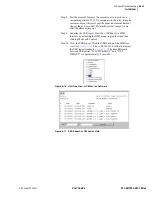
Page 205: ...d perform relay control functions The relay features a straightforward menu driven control structure presented on the front panel liquid crystal display LCD Front panel targets and other LED indicators give a quick look at SEL 421 Relay operation status You can perform often used control actions rapidly by using the large direct action pushbuttons All of these features help you operate the relay f...

Page 206: ...ent relay trip event Change the pushbutton and pushbutton LED labels with the slide in label carriers adjacent to the pushbuttons The SEL 421 Relay front panel features large operator control pushbutton switches with annunciator LEDs that facilitate local control Factory default settings associate specific relay functions with these eight direct action pushbuttons and LEDs Using SELOGIC control eq...

Page 207: ...unications port or use the Front Panel branch of the ACSELERATOR software settings tree view The maximum backlight time is one hour Obtain this 60 minute maximum backlight time by setting FP_TO to 60 or to OFF When the front panel times out the relay displays an automatic ROTATING DISPLAY described later in this section under Screen Scrolling on page 5 4 Navigating the Menus The SEL 421 Relay fron...

Page 208: ...peatedly returns you to the MAIN MENU If a status warning or event condition is active not acknowledged or reset the relay displays the full screen status warning or trip event screen in place of the MAIN MENU Screen Scrolling The SEL 421 Relay has two screen scrolling modes autoscrolling mode and manual scrolling mode After front panel time out the LCD presents each of the display screens in this...

Page 209: ...re 5 4 are representative values Figure 5 4 Sample ROTATING DISPLAY FUND_VI Fundamental Voltage and Current Screena Y N Y FUNDSEQ Fundamental seqUence Quantities Screen Y N N FUND_BK Fundamental Breaker Currents Screen Y N N a The default displays are RMS_I and FUND_VI Table 5 2 Metering Screens Enable Settings Sheet 2 of 2 Name Description Range Default NOTE The initial display can present only t...

Page 210: ... pressing the Up or Left pushbuttons switches the display to the previous screen In manual scrolling mode the display shows arrows at the top and bottom of the vertical scroll bar The screen arrows indicate that you can navigate between the different screens at will The relay retrieves data prior to displaying each new screen Unlike the autoscrolling mode the relay continues to update screen infor...

Page 211: ...priate interface hardware to connect the circuit breaker auxiliary contacts to IN201 to read the circuit breaker status Assume a 125 Vdc system and use the factory defaults for settings EICIS GINP GIND and GINDF see Control Input Assignment on page U 4 59 in the User s Guide In the Front Panel settings SET F enter the following after the Display Points and Aliases line 1 prompt 1 IN201 Circuit Bre...

Page 212: ...play point application example does not require a clear state so the clear state is blank If the Fast Meter test is not running and no other display points are active the relay shows a blank screen in the ROTATING DISPLAY Figure 5 6 Fast Meter Display Points Sample Screen FAST METER TEST ROTATING DISPLAY Press For Menu ...

Page 213: ...T ACCESS LEVEL Support Screens The relay displays special screens over the top of the menu or screen that you are using to control the relay or view data These screens are the contrast adjustment screen and the PASSWORD REQUIRED screen Contrast You can adjust the LCD screen contrast to suit your viewing angle and lighting conditions To change screen contrast press and hold the ESC pushbutton for o...

Page 214: ... access level the relay authorizes front panel access to the combination of access levels new level and all lower levels for which the password is valid The relay replaces the password screen with the menu screen that was active before the password validation routine When you enter Access Levels B P A O and 2 the Relay Word bit SALARM pulses for one second If you did not enter a valid password the...

Page 215: ...NU shown in Figure 5 11 allows you to choose the following metering screens corresponding to the relay metering modes RMS METER FUNDAMENTAL METER DEMAND METER if enabled ENERGY METER MAX MIN SYNCHRONISM CHECK if enabled Figure 5 11 METER MENU Screens METER EVENTS BREAKER MONITOR RELAY ELEMENTS LOCAL CONTROL SET SHOW RELAY STATUS VIEW CONFIGURATION DISPLAY TEST RESET ACCESS LEVEL MAIN MENU METER ME...

Page 216: ...sent the METER SUBMENU screen See Current and Voltage Source Selection on page R 1 2 in the Reference Manual and Global Settings on page R 9 3 in the Reference Manual for information on configuring global settings ESS NUMBK LINEI BK1I and BK2I Figure 5 12 METER SUBMENU The relay presents the meter screens in the order shown in each column of Figure 5 13 on page 5 13 and Figure 5 14 on page 5 14 On...

Page 217: ...3I0 x xxx x xxx SEQUENCE V kV V1 x xxx x xxx 3V2 x xxx x xxx 3V0 x xxx x xxx FUND LINE METER ACTIVE POWER MW A xx xxx x B xx xxx x C xx xxx x 3P xx xxx x REACTIVE MVAR A xx xxx x B xx xxx x C xx xxx x 3P xx xxx x FUND LINE METER APPARENT POWER MVA A xx xxx xx B xx xxx xx C xx xxx xx 3P xx xxx xx POWER FACTOR A x xx LEAD B x xx LEAD C x xx LEAD 3P x xx LEAD FUND LINE METER CURRENTS A IA x xxx xx xx...

Page 218: ...S1M xxx xxx V ANGLE1 xxx xxx SLIP1 xx xxx Hz SYNCH CHECK BREAKER 2 NVS2M xxx xxx V ANGLE2 xxx xxx SLIP2 xx xxx Hz ENERGY IN MWh A xx xxx xx B xx xxx xx C xx xxx xx 3P xx xxx xx ENERGY OUT MWh A xx xxx xx B xx xxx xx C xx xxx xx 3P xx xxx xx ENERGY METER ENERGY TOTAL MWh A xx xxx xx B xx xxx xx C xx xxx xx 3P xx xxx xx ENERGY METER RESET ENERGY NOW NO YES LAST ENERGY RESET MM DD YYYY HH MM SS CURRE...

Page 219: ...ok If you have two circuit breakers and have set NUMBK 2 the alarm submenu in Figure 5 16 appears first Use the navigation pushbuttons to choose either Circuit Breaker 1 or Circuit Breaker 2 Press ENT to view the selected circuit breaker monitor information An example of the Circuit Breaker 1 ALARM COUNTER screen for a single pole tripping circuit breaker is shown on the right side of Figure 5 16 ...

Page 220: ...ter this search menu the block cursor is at the beginning of the element name field and the highlight box in the alphanumeric field is around the letter A Use the navigation pushbuttons to move through the alphanumeric characters If the highlight is on one of the characters pressing ENT enters the character at the block cursor location in the element name field Next the block cursor moves automati...

Page 221: ...y displays an information message when you attempt to enter LOCAL CONTROL and the screen returns to the MAIN MENU after a short delay Local bit names that you have programmed see Example 5 3 on page 5 20 appear in the local control bit names field between BREAKER CONTROL and OUTPUT TESTING as shown in Figure 5 19 Use the Up and Down pushbuttons to highlight the local control action you want to per...

Page 222: ...control handle If the local bit is in the clear state the graphic control handle points to 0 if the local bit is in the set state the switch points to 1 You can program names or aliases for the local bit clear and set states these appear next to logical 0 and logical 1 respectively in the lower portion of the sample Bus Tie Interlock screens of Figure 5 21 Use the Up and Down pushbuttons to highli...

Page 223: ...ptional If your application requires a pulsed or momentary output you can activate an output pulse by setting the option at the end of the local bit command string to Y for Yes The default for the pulse state is N for No if you do not specify Y the local bit defaults at N and gives a continuous set or clear switch level Table 5 4 Local Bit Control Settingsa a n 1 32 Description Range Default Local...

Page 224: ...changes the state of this local bit to logical 0 when you save the settings To delete use the front panel settings When using a communications port and terminal use the text edit mode line setting editing commands at the Local Bits and Aliases prompt to go to the line that lists Local Bit 9 See Text Edit Mode Line Editing on page U 4 21 in the User s Guide for information on text edit mode line ed...

Page 225: ...ttings for DATE TIME have no settings instance screens In the GROUP screen move the highlight box to 3 and press ENT Proceed to selecting the settings category The GROUP submenu in Figure 5 23 is an example of settings Group 3 categories Once you have highlighted the settings category pressing ENT causes the relay to display the particular settings in that category The LINE CONFIGURATION screen in...

Page 226: ...igation pushbuttons answer YES to make the settings change s or NO to abort the settings change s Figure 5 23 SET SHOW Screens SET SHOW PORT GLOBAL GROUP ACTIVE GROUP 3 DATE TIME GROUP SELECT AN INSTANCE SELECT A CLASS M 1 2 3 ACTIVE 4 5 6 GROUP 3 SELECT A CATEGORY Line Configuration Relay Configuration Mho Phase Distance E Mho Phase Distance E Mho Ground Distance Zero Sequence Compen Ground Dista...

Page 227: ...group The relay performs a password validation test at this point to confirm that you have Breaker Access Level authorization or above If access is allowed and all the results of SELOGIC control equations SS1 SS6 are not logical 1 asserted then the relay displays the EDIT ACTIVE GROUP screen in Figure 5 25 The relay shows the active group and underlines the group number after NEW GROUP Use the Up ...

Page 228: ...e For a description of the LAST UPDATE SOURCE field see Configuring High Accuracy Timekeeping on page U 4 66 in the User s Guide Figure 5 27 Edit DATE and Edit TIME Screens To enable a high accuracy external time source connect a GPS receiver to the relay For a discussion of the IRIG and PPS timing modes in the SEL 421 Relay see Configuring High Accuracy Timekeeping on page U 4 66 in the User s Gu...

Page 229: ...n status warning and status failure messages see Relay Self Tests on page U 6 37 in the User s Guide Figure 5 28 Relay STATUS Screens RELAY STATUS RELAY STATUS RELAY STATUS SEL 421 R101 V0 Z001001 D20010315 Normal Status Warning Status Failure S N 2001001234 RELAY ENABLED NO FAILURES OR WARNINGS SEL 421 R101 V0 Z001001 D20010315 S N 2001001234 RELAY ENABLED TEMPERATURE WARNING SEL 421 R101 V0 Z001...

Page 230: ... the MAIN MENU Figure 5 29 VIEW CONFIGURATION Sample Screens FID SEL 421 R101 V0 Z001001 D20010315 PART NUMBER 04210615X22XXHX S N 200101234 SELBOOT BFID SLBT 421 R101 V0 Z001001 D20010315 CHECKSUM D97F CONFIGURATION INFO FIBER PORT NOT INSTALLED INTERFACE BOARDS BOARD 1 8 INPUTS 15 OUTPUTS BOARD 2 NOT INSTALLED EXTENDED FEATURES DNP ACTIVE CONFIGURATION INFO COMMUNICATIONS CARD MODEL SEL 2701 DES...

Page 231: ...o front panel functions As you progress through these menus the relay detects the existing password level and prompts you for valid passwords before allowing you access to levels greater than Access Level 1 see Password on page 5 10 in this section When you want to return the front panel to the lowest access level Access Level 1 highlight RESET ACCESS LEVEL item on the MAIN MENU Pressing ENT momen...

Page 232: ...he MAIN MENU and a status warning occurs or an event report triggers the relay shows automatic messages at the bottom of the active screen in the message area For example the message area shows RELAY STATUS WARNING for a status warning Figure 5 33 is an example of a status warning notification that appears in the message area of a LOCAL CONTROL local bit screen If a trip event occurs while you are...

Page 233: ...diately displays the full screen status alert regardless of the present front panel operating state The relay displays no further LCD screens until the status failure clears Should an unlikely status failure event occur contact your local Technical Service Center or an SEL factory representative see Factory Assistance on page U 6 43 in the User s Guide ...

Page 234: ...ation The relay reports these targets in event reports set the alias name listed in the report up to eight characters with settings TnLEDA After setting the target LEDs issue the TAR R command to reset the target LEDs For a concise listing of the default programming on the front panel LEDs see Front Panel Settings on page R 9 33 in the Reference Manual Use the slide in labels to mark the LEDs with...

Page 235: ...these LEDs remain illuminated for as long as you press TARGET RESET The target LEDs return to a normal operational state after you release the TARGET RESET pushbutton Lamp Test Function With LCD DISPLAY TEST Menu The LCD menus provide a front panel DISPLAY TEST mode This menu activated lamp test from the DISPLAY TEST menu does not reset the target LEDs see DISPLAY TEST on page 5 27 Other Target Re...

Page 236: ...lluminates if either the M3P or Z3G distance elements operated or if the high speed Zone 3 elements operated and the similar elements in Zone 1 and Zone 2 did not operate The ZONE 4 target illuminates if either the M4P or Z4G distance elements operated and the similar elements in Zone 1 Zone 2 and Zone 3 did not operate Phase s or Ground The phase s or ground targets illuminate according to the SE...

Page 237: ...f the SEL 421 Relay reclosing function The 79 RESET LED indicates that the relay recloser is in the reset or ready to reclose state for Circuit Breaker 1 Relay Word bit BK1RS is asserted The 79 LOCKOUT target illuminates when the relay has completed the reclose attempts unsuccessfully a drive to lockout condition or when other programmed lockout conditions exist If the 79 RESET and the 79 LOCKOUT ...

Page 238: ...The operator control pushbuttons and LEDs are programmable Figure 5 36 on page 5 35 describes the factory defaults for the four operator controls on the left side of the display and Figure 5 37 on page 5 36 describes the factory defaults for the operator controls on the right side of the display Using SELOGIC control equations you can readily change the default pushbutton and LED functions Use the...

Page 239: ...trol and operational requirements This programmability allows great flexibility and provides operator confidence and safety especially in indicating the status of functions that are controlled both locally and remotely Figure 5 36 Factory Default Operator Control Pushbuttons Left Side SELOGIC Factory Setting Operator Control Pushbutton LED Description Press this operator control pushbutton to enab...

Page 240: ...the automatic recloser The corresponding LED illuminates to indicate the RECLOSE ENABLED state Press this operator control pushbutton to close Circuit Breaker 1 The corresponding BREAKER CLOSED LED illuminates indicating that Circuit Breaker 1 is closed The MANUAL CLOSE ENABLED function above enables and disables the CLOSE pushbutton Press this operator control pushbutton to trip Circuit Breaker 1...

Page 241: ...ese occur The subsection Relay Troubleshooting on page 6 40 contains a quick reference table for common relay operation problems Topics tests and troubleshooting procedures presented in this section include the following Testing philosophy Testing features and tools Relay test connections Test methods Relay element tests selected elements Relay self tests Relay troubleshooting Factory assistance T...

Page 242: ...the power system and all auxiliary equipment Check control signal inputs and outputs Check breaker auxiliary inputs SCADA control inputs and monitoring outputs Use an ac connection test to verify that the relay current and voltage inputs are the proper magnitude and phase rotation Brief fault tests confirm that the relay settings and protection scheme logic are correct You do not need to test ever...

Page 243: ...determine whether the relay asserts outputs at the correct times and whether auxiliary equipment operates properly At each maintenance interval the only items to be tested are those that have not operated via fault conditions and otherwise during the maintenance interval The basis for this testing philosophy is simple you do not need to perform further maintenance testing for a correctly set and c...

Page 244: ...hanges occur because of alterations to relay settings and or differences in the signals applied to the relay You do not need to verify relay element operating characteristics as a part of maintenance checks SEL recommends that you limit maintenance tests on SEL relays according to the guidelines listed in Table 6 3 on page 6 3 You will spend less time checking relay operations that function correc...

Page 245: ...lues In addition metering shows many other quantities including the power system frequency FREQ and the voltage input to the station dc battery monitors Vdc1 and Vdc2 Compare these quantities against quantities from other devices of known accuracy The metering data are available at the serial ports from the SEL 5030 ACSELERATOR Software Program HMI and at the front panel LCD METER menu See MET on ...

Page 246: ...re detailed analysis See Event Summary on page A 3 28 in the Applications Handbookfor more information on the event summary SER Reports The relay provides an SER report that time tags changes in relay elements control inputs and control outputs Use the SER for convenient verification of the pickup and dropout of any relay element For a complete discussion of the SER see SER Sequential Events Recor...

Page 247: ...o electrostatic discharge ESD Undetectable permanent damage can result if you do not use proper ESD procedures Ground yourself your work surface and this equipment before removing any cover from this equipment If your facility is not equipped to work with these components contact SEL about returning this device and related SEL equipment for service Access the test interface by removing the relay f...

Page 248: ...ther the applied test voltages and currents produce correct relay operating quantities The UUT Database entries for the SEL 421 Relay in the SEL 5401 Relay Test System Software are shown in Table 6 4 and Table 6 5 Table 6 4 UUT Database Entries for SEL 5401 Relay Test System Software 5 A Relay Label Scale Factor Unit 1 IAW 75 A 2 IBW 75 A 3 ICW 75 A 4 IAX 75 A 5 IBX 75 A 6 ICX 75 A 7 VAY 150 V 8 V...

Page 249: ...emes Test Setup Test Source Connections For each relay element test you must apply ac voltage and current signals to the relay The text and figures in this subsection describe the test source connections you need for relay protection element checks You can use these connections to test protective elements and simulate all fault types Connections for Three Voltage Sources and Three Current Sources ...

Page 250: ...You can use the connections shown in Figure 6 3 to simulate phase to phase phase to ground and two phase to ground faults Use the connections shown in Figure 6 4 on page 6 11 to simulate three phase faults Figure 6 3 Test Connections Using Two Current Sources for Phase to Phase Phase to Ground and Two Phase to Ground Faults Three Phase Voltage and Current Test Sources IA VB IB VC IC VA IAW Z01 Z02...

Page 251: ...page 6 12 and Figure 6 6 on page 6 13 show connections to use when you have three voltage sources and a single current source You can use the connections shown in Figure 6 5 to simulate phase to ground faults Use the connections shown in Figure 6 6 to simulate phase to phase faults Three Phase Voltage and Current Test Sources IA VB IB VC IC VA IAW Z01 Z02 Z03 Z04 Z05 Z06 Z13 Z14 Z15 Z16 Z17 Z18 IB...

Page 252: ...lay Test Connections Figure 6 5 Test Connections Using a Single Current Source for a Phase to Ground Fault Three Phase Voltage and Current Test Sources IA VB IB VC IC VA IAW Z01 Z02 Z03 Z04 Z05 Z06 Z13 Z14 Z15 Z16 Z17 Z18 IBW ICW VAY VBY VCY Relay Rear Panel Secondary Voltage and Current Inputs ...

Page 253: ...lay Test Connections Figure 6 6 Test Connections Using a Single Current Source for a Phase to Phase Fault Three Phase Voltage and Current Test Sources IA VB IB VC IC VA IAW Z01 Z02 Z03 Z04 Z05 Z06 Z13 Z14 Z15 Z16 Z17 Z18 IBW ICW VAY VBY VCY Relay Rear Panel Secondary Voltage and Current Inputs ...

Page 254: ...ee Instantaneous Line Overcurrent Elements on page R 1 62 in the Reference Manual For this procedure you must have a serial terminal or computer with terminal emulation software and a variable current source for relay testing This example assumes that you have successfully established communication with the relay see Making an EIA 232 Serial Port Connection on page U 4 6 in the User s Guide for a ...

Page 255: ...nt Panel LCD You can use the front panel display and navigation pushbuttons to check Relay Word bit elements See Section 5 Front Panel Operations in the User s Guide for more information on using the relay front panel This procedure uses the 50P1 Phase Instantaneous Overcurrent element Use the factory defaults for the pickup level Table 6 6 on page 6 14 For more information on the 50P elements see...

Page 256: ... source to the relay Set the current output of a test source to zero output level Connect a single phase current output of the test source to the IAW analog input see Figure 6 5 on page 6 12 and Secondary Circuits on page U 2 5 in the User s Guide ELEMENT SEARCH A B C D E F G H I J K L M N O P Q R S T U V W X Y Z 0 1 2 3 4 5 6 7 8 9 ACCEPT BACKSPACE METER EVENTS BREAKER MONITOR RELAY ELEMENTS LOCA...

Page 257: ... Settings on page U 4 19 in the User s Guide In addition you need a variable current source suitable for relay testing Step 1 Prepare to control the relay with the ACSELERATOR software Establish communication check passwords and read relay settings see Making Settings Changes Initial Global Settings on page U 4 19 in the User s Guide Step 2 Set a pushbutton LED SELOGIC control equation Expand the ...

Page 258: ... for configuring control inputs and control outputs The Appendix A Relay Word Bits in the Reference Manual lists the names of the relay element logic outputs Testing the 50P1 Element With a Control Output This procedure shows how to set control output OUT105 to test the 50P1 Phase Instantaneous Overcurrent element Use the factory defaults for the pickup level see Table 6 6 on page 6 14 For more in...

Page 259: ...EL 421 Relay On the File menu click Send The ACSELERATOR software prompts you for the settings class you want to send to the relay as shown in the Group Select dialog box in Figure 6 12 Click the check box for Output Click OK The relay responds with the Transfer Status dialog box in Figure 6 12 If you see no error message the new settings are loaded in the relay NOTE The Relay Editor dialog boxes ...

Page 260: ...ment Use the factory defaults for the operating quantity pickup level curve time dial and electromechanical reset Table 6 7 The procedure in the following steps shows how to set the SER trigger lists to capture the selectable operating quantity time overcurrent element 51S1 operating times The procedure also shows how to set the torque control supervision for the 51S1 element The relay uses Equati...

Page 261: ... Guide Step 2 Set the selectable operating quantity time overcurrent element for test operation Open the Group 1 Relay Configuration Time Overcurrent branch of the Settings tree view see Figure 6 13 In the Time Overcurrent dialog box check that setting 51S1O Operating Quantity is at 3I0L Check the remaining element configurations against Table 6 7 on page 6 20 In addition set torque control 51S1TC...

Page 262: ...Events Recorder on page A 3 34 in the Applications Handbook Step 5 Save the new settings in the ACSELERATOR software On the File menu click Save Step 6 Upload the new settings to the SEL 421 Relay On the File menu click Send The ACSELERATOR software prompts you for the settings class you want to send to the relay as shown in the Group Select dialog box of Figure 6 15 Click the check box for Group ...

Page 263: ...rrent source to zero after the element time out Step 9 Examine the SER report Start the ACSELERATOR HMI interface by selecting the HMI menu top toolbar and then clicking Meter and Control Step 10 View the SER report Click the SER button of the HMI tree view see Figure 6 16 The ACSELERATOR software displays the SER report similar to Figure 6 17 The time difference between SER entries 51S1 PICKED UP...

Page 264: ...al tests and element verification confirm correct internal relay processing Selected Element Tests This subsection discusses tests of the following relay elements Overcurrent element Negative sequence instantaneous 50Q1 Directional element Negative sequence portion F32Q R32Q of the phase directional element F32P R32P Distance element Phase to phase mho element MBC2 of Zone 2 mho distance element M...

Page 265: ...d current element pickup setting If balanced currents are applied to the relay the relay reads 3I0 0 load conditions because the currents cancel in the calculation the relay does not pick up the ground overcurrent elements For testing apply current to a single phase of the relay causing the residual overcurrent elements to operate For example assume 1 A of current on A phase and zero current input...

Page 266: ...l see the Negative Sequence Instantaneous Overcurrent dialog box similar to Figure 6 19 For this test set the 50Q1P level to 1 00 Figure 6 19 Negative Sequence Instantaneous Overcurrent Element Settings ACSELERATOR Software Step 3 Upload the new setting to the SEL 421 Relay On the File menu click Send The ACSELERATOR software prompts you for the settings class you want to send to the relay as show...

Page 267: ...ate changes on the LCD screen from 50Q1 0 to 50Q1 1 Negative Sequence Directional Element for Phase Faults The SEL 421 Relay features a phase directional element represented by Relay Word bits F32P R32P to supervise the phase distance elements and to control phase directional elements The negative sequence directional element F32Q R32Q is a part of the phase directional element F32P R32P Whenever ...

Page 268: ...values that you need to apply to the relay to test the element For the negative sequence current I2 the result is Equation 6 4 when Equation 6 5 Multiply the quantities in Equation 6 4 by three to obtain 3I2 the negative sequence current that the relay processes With a fixed applied negative sequence voltage VA the relay negative sequence voltage is 3V2 Set Z2c Z2F to find the test current magnitu...

Page 269: ... that you have successfully established communication with the relay see Making an EIA 232 Serial Port Connection on page U 4 6 in the User s Guide for a step by step procedure In addition you must be familiar with relay access levels and passwords See Changing the Default Passwords on page U 4 8 in the User s Guide to change the default access level passwords and enter higher relay access levels ...

Page 270: ...st values in the relay Expand the Group 1 settings as shown in Figure 6 25 and select the Line Configuration button You will see the Line Configuration dialog box of Figure 6 25 Confirm the default settings of Z1MAG at 7 80 and Z1ANG at 84 00 Click the mark next to the Relay Configuration branch to expand that Settings branch Select the Directional button You will see the Directional dialog box si...

Page 271: ...Click the check box for Group 1 and for Breaker Monitor Click OK The ACSELERATOR software responds with a Transfer Status dialog box as in Figure 6 27 If you see no error message the new settings are loaded in the relay NOTE The Relay Editor dialog boxes shown in Figure 6 27 are for the SEL 421 Relay The SEL 421 1 Relay dialog boxes are similar Figure 6 27 Uploading Group 1 and Breaker Monitor Set...

Page 272: ...quation 6 7 on page 6 28 to determine the applied current angle ÐITEST Step 8 Apply a test current to confirm operation of R32Q and F32Q Connect a single current test source as shown in Figure 6 5 on page 6 12 Apply an A phase voltage of VA 18 0 Ð180 V secondary Set the current source for IA 0 0 Ð 96 A Slowly increase the magnitude of IA to apply the source test current Observe the RELAY ELEMENT L...

Page 273: ...hase distance protection each zone consists of phase to phase elements that the relay combines to produce a particular zone output For example the OR combination of MAB2 MBC2 and MCA2 produces the M2P Zone 2 mho phase element For more information on the mho phase elements and other distance elements see Section 1 Protection Functions in the Reference Manual and Section 1 Protection Application Exa...

Page 274: ...e 6 33 the angle of IB is the angle of ITEST and the angle of IC is 180 degrees from the angle of ITEST The test source current for IB is Equation 6 13 And the test source current for IC is Equation 6 14 Checking the MBC2 Portion of the M2P Phase Distance Element NOTE As you perform this test other protection elements can assert This causes the relay to assert other targets and possibly close cont...

Page 275: ...the text boxes for 52AA1 A Phase N O Contact Input BK1 52AB1 B Phase N O Contact Input BK1 and 52AC1 C Phase N O Contact Input BK1 The text boxes in Figure 6 24 on page 6 30 appear if Breaker Monitor setting BK1TYP 1 If BK1TYP 3 enter 1 in the 52AA1 N O Contact Input BK1 text box the other circuit breaker input boxes are dimmed Step 2 Set test values in the relay Expand the Group 1 settings as sho...

Page 276: ...se the navigation keys to highlight M and press ENT to enter character in the text input field Enter the B C and 2 characters in like manner Highlight ACCEPT and press ENT The relay displays the LCD screen containing the MBC2 element as shown in Figure 6 31 Figure 6 31 RELAY ELEMENTS LCD Screen Containing Element MBC2 Step 6 Set the magnitudes and angles of the test signals for a B phase to C phas...

Page 277: ...on early during the development of potential problems to avoid system failures For any status failure contact your Technical Service Center or the SEL factory immediately see Factory Assistance on page 6 43 The relay generates an automatic status report at the serial ports for a self test status failure if you set Port setting AUTO Y The relay issues a status message with a format identical to the...

Page 278: ... 938 Station A Serial Number 2001001234 FID SEL 421 R101 V0 Z001001 D20010315 CID 0x4572 Failures No Failures Warnings No Warnings Channel Offsets mV W Warn F Fail CH1 CH2 CH3 CH4 CH5 CH6 CH7 CH8 CH9 CH10 CH11 CH12 MOF 0 0 0 0 0 0 0 0 0 0 0 0 0 Power Supply Voltages V W Warn F Fail 3 3V_PS 5V_PS N5V_PS 15V_PS N15V_PS 3 28 4 91 4 93 14 70 14 79 Temperature 23 7 degrees Celsius Communication Interfa...

Page 279: ...r Ok or F Inac or Ok or F PPS IRIG or IRIG errbh errbh Enabled or Disabled Enabled or Disabled Enabled or Disabled Enabled or Disabled Enabled or Disabled F 0 5 F 0 5 F 0 5 F 0 5 F 0 5 F 0 5 yyyy Definitions for the items and fields in the Compressed ASCII configuration are listed below yyyy is the checksum x is text in the FID Firmware ID string ccrd is the communications card hex code errb is a ...

Page 280: ... for details on SEL 421 Relay commands and Section 9 Settings in the Reference Manual for details on relay settings Table 6 9 Troubleshooting Procedures Sheet 1 of 3 Possible Cause Diagnosis Solution Dark Front Panel Power is off Verify that substation battery power is operational Input power is not present Verify that power is present at the rear panel terminal strip Blown power supply fuse Repla...

Page 281: ...e halting com munications Type Ctrl Q to put the system in the XON state Terminal Displays Meaningless Characters Data speed baud rate is set incorrectly Check the terminal parameters configura tion See Communications Ports Connec tions on page U 2 44 in the User s Guide Terminal emulation is not optimal Try other terminal types including VT 100 and VT 52 terminal emulations System Does Not Respon...

Page 282: ...he Status Warning If repeated warn ings occur take preventive action A D converter failure LCD displays STATUS FAILURE screen Contact the SEL factory or your Technical Service Center Power Supply Voltage Status Failure Power supply voltage s are out of tolerance LCD displays STATUS FAILURE screen Contact the SEL factory or your Technical Service Center A D converter failure LCD displays STATUS FAI...

Page 283: ...r comments please contact us at Schweitzer Engineering Laboratories Inc 2350 NE Hopkins Court Pullman WA USA 99163 5603 Tel 509 332 1890 Fax 509 332 7990 Internet www selinc com You can also contact your local Technical Service Center Telephone us at 509 332 1890 or visit the SEL web page http www selinc com techsvc htm to locate your Technical Service Center We guarantee prompt courteous and prof...

Page 284: ...This page intentionally left blank ...
Page 285: ...ng data from the relay simulta neously with a serial port terminal session This firmware differs from the previous version as follows SEL 421 R102 V0 Z002001 D20020403 SEL 421 1 R102 V0 Z002001 D20020403 Initial Release with Synchrophasor Mea surement capability to the SEL 421 not in the SEL 421 1 Added VAZ VBZ VCZ settings options to SYNCP Added VAY VBY VCY settings options to SYNCS1 SYNCS2 and A...

Page 286: ...This page intentionally left blank ...

Page 287: ...monitoring ac ripple provides an indication of whether the substation battery charger has failed Acceptance Testing Testing that confirms that the relay meets published critical performance specifications and requirements of the intended application Such testing involves testing protection elements and logic functions when qualifying a relay model for use on the utility system Access Level A relay...

Page 288: ...t in place of the Relay Word bit making the SER report easier to review Analog Quantities Variables represented by such fluctuating measurable quantities as temperature frequency current and voltage AND Operator Logical AND An operator in Boolean SELOGIC control equations that requires fulfillment of conditions on both sides of the operator before the equation is true ANSI Standard Device Numbers ...

Page 289: ...c developed to control auto dial modems from an ASCII terminal usually EIA 232 connected or a PC personal computer containing software allowing emulation of such a terminal Autoconfiguration The ability to determine relay type model number metering capability port ID baud rate passwords relay elements and other information that an IED an SEL 2020 2030 communications processor needs to automaticall...

Page 290: ... devices See CVT Checksum A method for checking the accuracy of data transmission involving summation of a group of digits and comparison of this sum to a previously calculated value CID Checksum identification of the firmware Circuit Breaker Failure Logic This logic within the SEL 421 Relay detects and warns of failure or incomplete operation of a circuit breaker in clearing a fault or in perform...

Page 291: ...h incoming pulses or allow you to require that an input take a state for a certain period before reacting to the new state Contact Input See Control input Contact Output See Control output Coordination Timer A timer that delays an overreaching element so that a downstream device has time to operate Control Input Relay inputs for monitoring the state of external circuits Connect auxiliary relay and...

Page 292: ...sults from the physical phenomenon preventing an instantaneous change of current in an inductive circuit DCB Directional Comparison Blocking A communications assisted protection scheme A fault occurring behind a sending relay causes the sending relay to transmit a blocking signal to a remote relay the blocking signal interrupts the tripping circuit of the remote relay and prevents tripping of the ...

Page 293: ...of the demand meter time constant in demand metering DNP Distributed Network Protocol Manufacturer developed hardware independent communications protocol Dropout Time The time measured from the removal of an input signal until the output signal deasserts You can set the time in the case of a logic variable timer or the dropout time can be a result of the characteristics of an element algorithm as ...

Page 294: ...to bring all cells to a uniform output ESD Electrostatic Discharge The sudden transfer of charge between objects at different potentials caused by direct contact or induced by an electrostatic field Ethernet A network physical and data link layer defined by IEEE 802 2 and IEEE 802 3 Event History A quick look at recent relay activity that includes a standard report header event number date time an...

Page 295: ...re The nonvolatile program stored in the relay that defines relay operation Flash Memory A type of nonvolatile relay memory used for storing large blocks of nonvolatile data Flashover A disruptive discharge over the surface of a solid dielectric in a gas or liquid Float High The highest charging voltage supplied by a battery charger Float Low The lowest charging voltage supplied by a battery charg...

Page 296: ...stance Fault resistance that can consist of ground path resistance typically in tower footing resistance and tree resistance Guard Present Delay A timer that determines the minimum time before the relay reinstates permissive tripping following a loss of channel condition in the DCUB communications assisted tripping scheme relay setting GARD1D GUI Graphical user interface Hexadecimal Address A regi...

Page 297: ...d abrupt spurious variations in duration magnitude or frequency L R Circuit inductive resistive ratio Latch Bits Nonvolatile storage locations for binary information LED Light emitting diode Used as indicators on the relay front panel Left Side Value LVALUE Result storage location of a SELOGIC control equation Line Impedance The phasor sum of resistance and reactance in the form of positive sequen...

Page 298: ...of the maximum and minimum of each value along with the date and time that each maximum and minimum occurred Mechanical Operating Time Time between trip initiation or close initiation and the change in status of an associated circuit breaker auxiliary 52A normally open contacts Mho Characteristic A directional distance relay characteristic that plots a circle for the basic relay operation characte...

Page 299: ...ance from neutral to ground on a device such as a generator or transformer No Current Residual Current Circuit Breaker Failure Protection Logic Logic for detecting and initiating circuit breaker failure protection with a logic transition or when a weak source drives the fault or a high resistance ground fault occurs Nondirectional Start A blocking signal provided by nondirectional overcurrent elem...

Page 300: ...d the B phase voltage lags the C phase voltage by 120 Phase Selection Ability of the relay to determine the faulted phase or phases Pickup Time The time measured from the application of an input signal until the output signal asserts You can set the time as in the case of a logic variable timer or the pickup time can be a result of the characteristics of an element algorithm as in the case of an o...

Page 301: ...n of relay protection element and trip close logic processing and deenergization of all control outputs PT Potential transformer Also referred to as a voltage transformer or VT PTR Potential transformer ratio Quadrilateral Characteristic A distance relay characteristic on an R X diagram consisting of a directional measurement reactance measurement and two resistive measurements Qualifier Code Spec...

Page 302: ...rcuit breaker after the failure of an initial attempt to open these contacts Reverse Fault A fault operation behind a relay terminal Rising Edge Transition from logical 0 to logical 1 or the beginning of an operation RMS Root mean square This is the effective value of the current and voltage measured by the relay accounting for the fundamental frequency and higher order harmonics in the signal Rol...

Page 303: ...erts away from devices or apparatus SIN Operator Operator in math SELOGIC control equations that provides the sine function Single Pole Trip A circuit breaker trip operation that occurs when one pole of the three poles of a circuit breaker opens independently of the other poles SIR Source to line impedance ratio SOTF Switch Onto Fault Protection Logic Logic that provides tripping if a circuit brea...

Page 304: ...rature value for a specified time Three Phase Fault A fault involving all three phases of a three phase power system Three Pole Trip A circuit breaker operation that occurs when the circuit breaker opens all three poles at the same time Time Delay on Pickup The time interval between initiation of a signal at one point and detection of the same signal at another point Time Dial A control that gover...

Page 305: ...l port and a terminal Volatile Storage A storage device that cannot retain data following removal of relay power VT Voltage transformer Also referred to as a potential transformer or PT Warm Start The reset of a running system without removing and restoring power Weak Infeed Logic Logic that permits rapid tripping for internal faults when a line terminal has insufficient fault current to operate p...

Page 306: ...n both systems Zero Sequence Overcurrent Element Overcurrent protection that operates at conditions exceeding a threshold of system unbalance Zero Sequence Voltage Polarized Directional Element An element that provides directionality by the sign plus or minus of the measured zero sequence impedance Z Number That portion of the relay FID string that identifies the proper ACSELERATOR software relay ...

Page 307: ...lication example A 1 136 A 1 150 external recloser R 2 10 logic diagrams R 2 32 R 2 40 one circuit breaker R 2 5 R 2 10 single and three pole reclose R 2 7 application example A 1 140 A 1 146 single pole reclose R 2 5 R 2 6 three pole reclose R 2 6 R 2 7 application example A 1 136 A 1 139 trip logic R 2 10 Relay Word bits R 2 31 R 2 32 settings R 2 29 R 9 25 R 9 27 states R 2 2 R 2 4 lockout R 2 ...

Page 308: ...28 R 8 32 OPEN n R 8 32 PASSWORD R 8 33 R 8 34 PULSE U 6 6 R 8 36 QUIT R 8 36 SER U 4 50 A 3 34 A 3 35 R 8 36 R 8 38 SET R 8 38 R 8 42 STATUS U 6 37 U 6 38 R 8 45 R 8 47 SUMMARY A 3 30 R 8 47 R 8 48 TARGET U 6 6 R 8 48 R 8 49 TEST DB U 6 6 R 8 49 R 8 50 TEST DNP U 6 7 R 8 50 R 8 51 TEST FM U 6 7 R 8 51 R 8 53 TIME Q U 4 68 U 4 69 R 8 53 TRIGGER U 4 39 A 3 5 R 8 54 VERSION R 8 54 R 8 55 Commissioni...

Page 309: ...Events Recorder CST Command U 6 39 CSUMMARY Command A 3 30 A 3 31 R 8 15 R 8 17 See also Event Summary Current and Voltage Source Selection U 1 7 R 1 2 R 1 8 application example A 1 4 A 1 5 A 1 22 A 1 23 A 1 56 A 1 89 ESS N single circuit breaker R 1 2 ESS 1 single circuit breaker R 1 2 R 1 3 ESS 2 single circuit breaker R 1 3 R 1 4 ESS 3 double circuit breaker R 1 4 R 1 5 ESS 4 double circuit bre...

Page 310: ...n example ACSELERATOR software U 4 41 U 4 42 terminal U 4 42 terminal A 3 32 A 3 33 Event Report U 1 3 A 3 12 A 3 28 See also Event largest current A 3 16 A 3 19 trigger row A 3 16 A 3 19 ACSELERATOR software A 3 14 analog section A 3 14 A 3 19 Compressed ASCII CEVENT A 3 24 A 3 28 application example A 3 24 A 3 28 currents and voltages A 3 15 digital section A 3 19 A 3 21 label header A 3 20 read...

Page 311: ... communications card U 2 15 See also Communications Card INT1 U 2 12 U 2 15 INT5 U 2 12 U 2 15 INT6 U 2 12 U 2 15 interface board inputs U 2 12 interface board installation U 2 13 U 2 15 interface board jumpers U 2 21 U 2 25 See also Jumpers interface board outputs U 2 13 jumpers U 2 21 See also Jumpers U 2 21 main board U 2 9 Installation U 2 31 U 2 46 dimensions U 2 32 panel mounting U 2 32 phys...

Page 312: ... 3 Monitor Circuit Breaker See Circuit Breaker monitor MOV control outputs U 2 6 Multidrop Network A 6 4 O OOSB See Out of Step OOST See Out of Step OPEN n Command R 8 32 Open Phase Detection Logic R 1 13 Operator Control LEDs U 5 34 U 5 36 See also LEDs factory defaults U 5 35 U 5 36 Operator Control Pushbuttons U 5 34 U 5 36 See also Pushbuttons LEDs factory defaults U 5 34 Oscillography U 1 3 U...

Page 313: ... 4 54 terminal U 4 52 U 4 53 include TESTPUL in ER A 3 5 no event data A 3 4 Pushbuttons factory defaults U 5 34 front panel U 5 2 labels U 5 34 LEDs See Operator Control LEDs navigation U 5 3 U 5 4 operator control U 5 34 U 5 36 programming U 5 34 U 5 35 Q Quadrilateral Ground Distance Elements R 1 51 R 1 54 application example A 1 28 A 1 32 A 1 93 A 1 97 logic diagrams R 1 53 R 1 54 polarization...

Page 314: ... 17 class U 4 15 U 4 17 date U 5 24 R 8 17 from front panel U 4 27 U 4 30 U 5 21 U 5 24 application example U 4 27 U 4 30 instance U 4 15 U 4 17 reduction U 1 4 SER U 4 47 See also SER Sequential Events Recorder structure U 4 16 terminal U 4 18 U 4 25 application example U 4 19 U 4 20 U 4 22 U 4 25 TERSE U 4 20 text edit mode U 4 21 U 4 25 time U 5 24 R 8 53 SIR A 1 6 A 1 25 A 1 58 R 1 37 SOTF See...

Page 315: ...necting U 4 67 IRIG B U 2 10 Time Out front panel U 5 3 TIME Q Command U 4 68 U 4 69 R 8 53 Time Synchronization U 1 3 See also Time DNP 3 0 R 6 8 IRIG B U 4 66 A 6 2 A 6 5 PPS U 4 66 Time Overcurrent Curves R 1 74 R 1 83 See also Overcurrent Elements Time Overcurrent Elements See Overcurrent Elements Timers See SELOGIC Control Equations Time Synchronized Measurements A 4 1 A 4 10 See also Time Sy...

Page 316: ...ction size U 2 38 U 4 4 Z Zero Sequence Current Compensation R 1 46 R 1 51 application example A 1 9 A 1 32 A 1 33 A 1 64 A 1 65 A 1 97 A 1 99 Zone Time Delay R 1 59 R 1 61 common timing R 1 59 application example A 1 9 A 1 33 A 1 65 A 1 100 independent timing R 1 59 logic diagram R 1 61 Zone Level Direction A 1 106 application example A 1 36 A 1 70 ...

Page 317: ...t number from 01 32 COPY m n Copy settings between instances in the same class m and n are instance numbers for example m 1 is Group 1 n 2 is Group 2 CSER SER command for the Compressed ASCII response CSTATUS STATUS command for the Compressed ASCII response CSUMMARY SUMMARY command for the Compressed ASCII response DATE Display and set the date DNAME X ASCII names of all relay digital I O Fast Met...

Page 318: ... database Fast Meter TIME Display and set the internal clock TRIGGER Initiate a data capture and record an event report VERSION Display the relay hardware and software configurations VIEW 1 View data from the communications card database a See Section 8 ASCII Command Reference on page R8 1 in Reference Manual b For help on a specific command type HELP command Enter at an ASCII terminal communicati...

Reviews: