U.2.2
SEL-421/SEL-421-1 Relay
User’s Guide
Date Code 20020501
Installation
Shared Configuration Attributes
Shared Configuration Attributes
There are common or shared attributes among the many possible
configurations of SEL-421 Relays. This section discusses the main shared
features of the relay.
Relay Sizes
SEL produces the SEL-421 Relay in horizontal and vertical rack-mount
versions and horizontal and vertical panel-mount versions. Relay sizes
correspond to height in rack units, U, where U is approximately 1.75 inches or
44.45 mm. The SEL-421 Relay is available in 3U, 4U, and 5U sizes.
Front-Panel
Templates
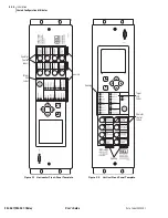
The horizontal front-panel template shown in
is the
same for all 3U, 4U, and 5U horizontal versions of the relay. The vertical
front-panel template (shown in
) is the same for all 3U,
4U, and 5U vertical versions of the relay.
The SEL-421 Relay front panel has three pockets for slide-in labels: one
pocket for the Target LED label, and two pockets for the Operator Control
labels.
shows the front-panel pocket areas and
openings for typical horizontal and vertical relay orientations; dashed lines
denote the pocket areas. See
Changing Configurable Front-Panel Labels on
for information on reconfiguring front-panel LED and pushbutton
labels.
Rear Panels
Rear panels are identical for the horizontal and the vertical configurations of
the relay.
is an example of a rear panel for a 3U relay
with fixed terminal block analog inputs.
shows a rear
panel for a 3U relay with Connectorized
®
analog inputs. See
for representative 3U, 4U, and 5U relay rear panels
(large drawings are in
).
Connector Types
Screw Terminal Connectors-I/O and Monitor/Power
Connect to the relay I/O and Monitor/Power terminals on the rear panel
through screw terminal connectors. You can remove the entire screw terminal
connector from the back of the relay to disconnect relay I/O, DC Battery
Monitor, and Power without removing each wire connection. The screw
terminal connectors are keyed (see
), so you can
replace the screw terminal connector on the rear panel only at the location
from which you removed the screw terminal connector. In addition, the
receptacle key prevents you from inverting the screw terminal connector. This
feature makes relay removal and replacement easier.
Secondary Circuit Connectors
Fixed Terminal Blocks
Connect PT and CT inputs to the fixed terminal blocks in the bottom row of
the relay rear panel. You cannot remove these terminal blocks from the relay
rear panel. These terminals offer a secure high-reliability connection for PT
and CT secondaries.
Summary of Contents for SEL-421
Page 8: ...This page intentionally left blank ...
Page 30: ...This page intentionally left blank ...
Page 110: ...This page intentionally left blank ...
Page 204: ...This page intentionally left blank ...
Page 284: ...This page intentionally left blank ...

