U.2.41
Date Code 20020501
User’s Guide
SEL-421/SEL-421-1 Relay
Installation
Connection
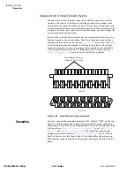
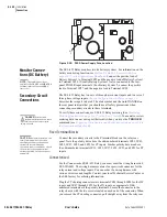
panel. As you remove the connector, internal mechanisms within the
connector separately short each power system current transformer. You can
install these connectors in only one orientation.
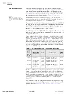
Plug the PT voltage connectors into terminals #Z13 to #Z18 for the VY inputs,
and #Z19 to #Z24 for the VZ inputs, as appropriate. Odd numbered terminals
are the polarity terminals. You can install these connectors in only one
orientation.
Control Circuit
Connections
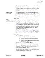
You can configure the SEL-421 Relay with many combinations of control
inputs and control outputs. See
for information about I/O configurations. This
subsection provides details about connecting these control inputs and outputs.
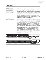
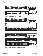
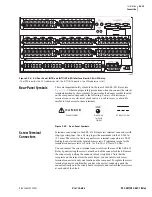
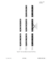
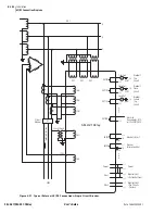
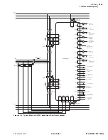
Refer to
, and
for representative rear-panel screw terminal connector locations.
Control Inputs
NOTE:
The combined voltages
applied to the INnnn and OUTnnn
terminals must not exceed 600 V (rms
or dc).
The control input connections on the rear-panel I/O screw terminal connectors
are polarity sensitive. A + indication appears over each pair of control inputs.
Connect the positive sense of the control input to the + terminal. Although you
cannot damage these inputs with a reverse polarity connection, a reverse
polarity connection will cause the relay internal A/D converter to measure the
input voltage incorrectly and the relay will no longer detect input changes. See
for more information.
Note that the main board I/O control inputs have one set of two inputs that
share a common input leg. These inputs are IN106 and IN107 found on
terminals #A30, #A31, and #A32.
To assign the functions of the control inputs, see
and Outputs on page U.4.52 in the User’s Guide
, or the
SET G
command in
SET on page R.8.38 in the Reference Manual
for more details. You can also
use the
AC
SEL
ERATOR
S
oftware to set and verify operation of the inputs.
Control Outputs
The SEL-421 Relay has three types of outputs:
➤
Standard outputs (example: main board OUT104)
➤
Hybrid (high-current-interrupting) outputs (example: main
board OUT101)
➤
Fast Hybrid (fast high-current-interrupting) outputs (example:
INT5 board OUT201, or OUT301)
See
for more information.
You can connect the Standard outputs and the Fast Hybrid (fast high-current-
interrupting) outputs in either ac or dc circuits. Connect the Hybrid (high-
current-interrupting) outputs to dc circuits only. The screw terminal connector
legends alert you about this requirement by showing polarity marks on the
Hybrid (high-current-interrupting) contacts.
Form A (SPST NO) contacts comprise the majority of the control outputs.
Two pairs of Form C (DPST CO) contacts are on the main board, the INT1 I/O
interface board, and the INT6 I/O interface board.
Summary of Contents for SEL-421
Page 8: ...This page intentionally left blank ...
Page 30: ...This page intentionally left blank ...
Page 110: ...This page intentionally left blank ...
Page 204: ...This page intentionally left blank ...
Page 284: ...This page intentionally left blank ...

