U.2.43
Date Code 20020501
User’s Guide
SEL-421/SEL-421-1 Relay
Installation
Connection
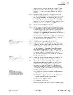
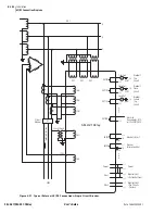
The relay pulses the SALARM Relay Word bit for software programmed
conditions; these include settings changes, access level changes, and alarming
after three unsuccessful password entry attempts. You can add the software
alarm SALARM to the alarm output by entering the following SEL
OGIC
control equation:
OUT108 :=
NOT (HALARM OR SALARM)
Tripping and Closing Outputs
To assign the control outputs for tripping and closing, see
Tripping and Closing on page U.4.57 in the User’s Guide
. In addition, you can
use the
SET O
command; see
SET on page R.8.38 in the Reference Manual
for more details. You can also use the front panel to set and verify operation of
the outputs. See
SET/SHOW on page U.5.21 in the User’s Guide
TIME Input
Connections
IRIG-B Input Connection
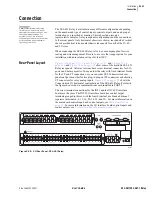
The SEL-421 Relay accepts a demodulated IRIG-B signal through two types
of rear-panel connectors. These IRIG-B inputs are through the BNC connector
labeled TIME IRIG-B or through Pin 4 (+) and Pin 6 (–) of the rear-panel
9-pin D-subminiature connector PORT 1. See
for other DE-9 connector pinouts and additional
details. These inputs accept the dc shift time code generator output
(demodulated) IRIG-B signal with positive edge on the time mark. For more
information on IRIG-B and the SEL-421 Relay, see
.
The BNC IRIG-B input and the PORT 1 IRIG-B input circuit connect to a
330
W
resistor in series with an optocoupler input diode. The optocoupler
input diode forward voltage drop is about 1.5 V. Driver circuits should source
approximately 10 mA through the circuit for the ON state. When using the
PORT 1 input, ensure that you connect Pins 4 and 6 with the proper polarity.
For ease of connection or for long runs from the IRIG-B generator to the
SEL-421 Relay, use the BNC IRIG-B input. Connect a 50
W
coaxial cable
assembly with a male BNC connector to the IRIG-B input of the SEL-421
Relay and the other end of the coaxial cable to the GPS receiver or other
IRIG-B generation equipment.
Where distance between the SEL-421 Relay and the IRIG-B sending device
exceeds the cable length recommended for conventional EIA-232 metallic
conductor cables, you can use transceivers to provide isolation and to
establish communication to remote locations. Conventional fiber-optic and
telephone modems do not support IRIG-B signal transmission. Use the
SEL-2810 transceiver to provide long distance delivery of the IRIG-B signal
to the SEL-421 Relay. The SEL-2810 includes a channel for the IRIG-B time
code. These transceivers enable you to synchronize time precisely from IRIG-
B time code generators (such as the SEL-2020 Communications Processor)
over a fiber-optic communications link.
Summary of Contents for SEL-421
Page 8: ...This page intentionally left blank ...
Page 30: ...This page intentionally left blank ...
Page 110: ...This page intentionally left blank ...
Page 204: ...This page intentionally left blank ...
Page 284: ...This page intentionally left blank ...

