U.2.44
SEL-421/SEL-421-1 Relay
User’s Guide
Date Code 20020501
Installation
Connection
1k PPS Input Connection
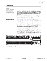
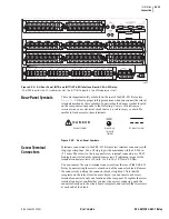
The SEL-421 Relay accepts a 1k PPS (or 1000 PPS) input from a GPS
receiver/time source through the rear-panel BNC jack labeled 1k PPS. (For
PPS mode, you must also supply a locked IRIG-B input.) For more
information on 1k PPS and the SEL-421 Relay, see
.
The 1k PPS port input impedance is 50
W
. Use a BNC cable assembly to
connect the 1k PPS signal from the GPS receiver/time source to the rear-panel
BNC jack labeled 1k PPS. Typical input levels are approximately 2.5 Vdc into
50
W
(open circuit 0–5 Vdc). See
Time Inputs on page U.1.11 in the User’s
for complete 1k PPS input specifications. For high-accuracy timing
applications, be sure to match the lengths and propagation delays of the
coaxial cables carrying the IRIG-B and 1k PPS signals to the SEL-421 Relay
inputs.
Replacing the
Lithium Battery
You can replace a bad lithium battery in the SEL-421 Relay. Perform the
following steps to replace the lithium battery.
Step 1. Remove the relay from service. Follow your company standard
procedure for removing a relay from service. Disconnect power
from the SEL-421 Relay. Remove the relay from the rack or
panel. Retain the GND connection, if possible, and ground the
equipment to an ESD mat.
Step 2. Remove the front panel from the SEL-421 Relay.
Step 3. Disconnect power, interface board cable(s), and input board
analog cable from the main board.
Step 4. Pull out the drawout tray containing the main board.
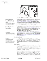
Step 5. Locate the lithium battery. The lithium battery is at the front of
the main board. See
Step 6. Remove the spent battery from beneath the clip of the battery
holder. Replace the battery with an exact replacement. Use a
3 V lithium coin cell, Ray-O-Vac
®
No. BR2335 or equivalent.
The positive side (+) of the battery faces up.
Step 7. Reinstall the SEL-421 Relay main board drawout tray.
Step 8. Reattach the power cable, interface board cable(s), and input
board analog cable.
Step 9. Reattach the front panel
Step 10. Set the relay date and time via the communications ports or
front panel (See
Making Simple Settings Changes on
page U.4.15 in the User’s Guide
).
Step 11. Follow your company standard procedure to return the relay to
service.
Communications
Ports Connections
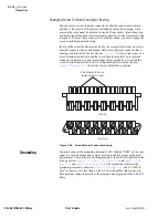
The SEL-421 Relay has three rear-panel EIA-232 serial communications ports
labeled PORT 1, PORT 2, and PORT 3 and one front-panel port, PORT F. For
information on serial communications, see
page U.4.5 in the User’s Guide
,
Serial Communication on page R.4.3 in the
Serial Port Hardware Protocol on page R.5.2 in the
DANGER:
Disconnect or
de-energize all external
connections before opening this
device. Contact with hazardous
voltages and currents inside this
device can cause electrical shock
resulting in injury or death.
!
WARNING:
Have only
qualified personnel service this
equipment. If you are not qualified to
service this equipment, you can
injure yourself or others, or cause
equipment damage.
!
CAUTION:
Equipment
components are sensitive to
electrostatic discharge (ESD).
Undetectable permanent damage
can result if you do not use proper
ESD procedures. Ground yourself,
your work surface, and this
equipment before removing any
cover from this equipment. If your
facility is not equipped to work with
these components, contact SEL
about returning this device and
related SEL equipment for service.
!
CAUTION:
There is danger of
explosion if the battery is
incorrectly replaced. Replace only
with Ray-O-Vac
®
no. BR2335 or
equivalent recommended by
manufacturer. Dispose of used
batteries according to the
manufacturer’s instructions.
!
Summary of Contents for SEL-421
Page 8: ...This page intentionally left blank ...
Page 30: ...This page intentionally left blank ...
Page 110: ...This page intentionally left blank ...
Page 204: ...This page intentionally left blank ...
Page 284: ...This page intentionally left blank ...


