U.5.35
Date Code 20020501
User’s Guide
SEL-421/SEL-421-1 Relay
Front-Panel Operations
Front-Panel Operator Control Pushbuttons
processor templates for printing slide-in labels. See
page 2.26 in Section 2: Installation
for more information on changing the
slide-in labels.
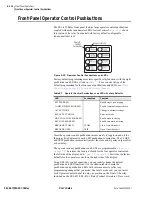
The SEL-421 Relay has two types of outputs for each of the front-panel
pushbuttons. Relay Word bits represent the pushbutton presses. One set of
Relay Word bits follows the pushbutton and another set pulses for one
processing interval when the button is pressed. Relay Word bits PB1 through
PB8 are the “follow” outputs of operator control pushbuttons. Relay Word bits
PB1_PUL through PB8_PUL are the pulsed outputs.
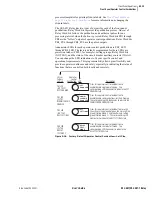
Annunciator LEDs for each operator control pushbutton are PB1_LED
through PB8_LED. The factory defaults programmed for these LEDs are
protection latches (PLT01, for example), settings groups, Relay Word bits
(NOT SG1), and the status of the circuit breaker auxiliary contacts (52AA1).
You can change the LED indications to fit your specific control and
operational requirements. This programmability allows great flexibility and
provides operator confidence and safety, especially in indicating the status of
functions that are controlled both locally and remotely.
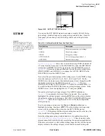
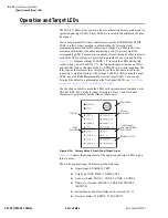
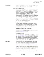
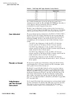
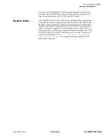
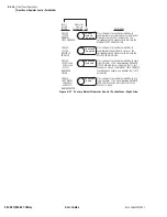
Figure 5.36
Factory Default Operator Control Pushbuttons—Left Side.
SEL
OGIC
Factory
Setting
Operator
Control
Pushbutton LED
Description
Press this operator control pushbutton to
enable/disable single-pole tripping. The
corresponding LED illuminates to indicate the SPT
ENABLED state.
Press this operator control pushbutton to
enable/disable communications-assisted tripping.
The corresponding LED illuminates to indicate the
COMM SCHEME ENABLED state.
Press this operator control pushbutton to switch
the active setting group between the main setting
group (Setting Group 1) and the alternate setting
group (Setting Group 2). The corresponding LED
illuminates to indicate the ALT SETTINGS state.
Press this operator control pushbutton to
enable/disable the relay test mode. The
corresponding LED illuminates to indicate the
RELAY TEST MODE state.
PB1_LED
= NOT E3PT
#SPT ENABLED
SPT
ENABLED
PB2_LED
= PLT02
#COMM SCHEME
ENABLED
COMM
SCHEME
ENABLED
PB4_LED
= PLT04
#RELAY
TEST MODE
RELAY
TEST
MODE
PB3_LED
= NOT SG1
#ALT SETTINGS
ALT
SETTINGS
Summary of Contents for SEL-421
Page 8: ...This page intentionally left blank ...
Page 30: ...This page intentionally left blank ...
Page 110: ...This page intentionally left blank ...
Page 204: ...This page intentionally left blank ...
Page 284: ...This page intentionally left blank ...

