U.6.7
Date Code 20020501
User’s Guide
SEL-421/SEL-421-1 Relay
Testing and Troubleshooting
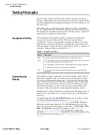
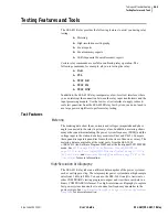
Testing Features and Tools
command effectively; see
Communications Card Database on page R.4.6 in
for more information.
TEST DNP
Command
Use the
TEST DNP
command to test the DNP 3.0 interface. Values you enter
in the DNP map are “override values.” Use the
TEST DNP
command to write
override values in the DNP map. For more information on DNP 3.0 and the
SEL-421 Relay, see
Section 6: DNP 3.0 Communications in the Reference
TEST FM
Command
Use the
TEST FM
command to override normal Fast Meter quantities for
testing purposes. You can only override “reported” Fast Meter values (per-
phase voltages and currents). You cannot directly test Fast Meter values that
the relay derives from the reported values (power, sequence components, and
so on). For more information on Fast Meter and the SEL-421 Relay, see
Section 5: SEL Communications Protocols in the Reference Manual
Low-Level
Test Interface
The SEL-421 Relay has a low-level test interface between the calibrated input
module and the processing module. You can check the relay in two ways: by
using secondary injection testing, or by applying low-magnitude ac voltage
signals to the low-level test interface.
Connection
CAUTION:
Equipment
components are sensitive to
electrostatic discharge (ESD).
Undetectable permanent damage
can result if you do not use proper
ESD procedures. Ground yourself,
your work surface, and this
equipment before removing any
cover from this equipment. If your
facility is not equipped to work with
these components, contact SEL
about returning this device and
related SEL equipment for service.
!
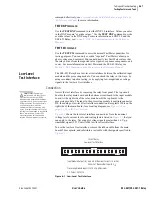
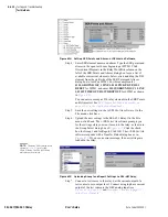
Access the test interface by removing the relay front panel. The top circuit
board is the relay main board and the bottom circuit board is the input module
board. At the right side of the relay main board (the top board) is the
processing module. The input to the processing module is multipin connector
J20, the analog or low-level test interface connection. Receptacle J20 is on the
right side of the main board; for a locating diagram, see
page U.2.18 in the User’s Guide
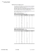
shows the low-level interface connections. Note the nominal
voltage levels, current levels, and scaling factors listed in
that you
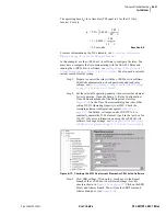
can apply to the relay. Never apply voltage signals greater than 6.6 Vp-p
sinusoidal signal (2.33 Vrms) to the low-level test interface.
To use the low-level test interface, remove the ribbon cable from the main
board J20 receptacle, and substitute a test cable with the signals specified in
Figure 6.1
Low-Level Test Interface.
U.S. Patent 5,479,315.
Input Module Output (J3): 66.6 mV At Nominal Current (1 A or 5 A).
SEL-421 Relay
Low-Level Test Interface
446 mV at Nominal Voltage (67 V
LN
).
Processing Module Input (J20): 6.6 Vp-p Maximum.
Summary of Contents for SEL-421
Page 8: ...This page intentionally left blank ...
Page 30: ...This page intentionally left blank ...
Page 110: ...This page intentionally left blank ...
Page 204: ...This page intentionally left blank ...
Page 284: ...This page intentionally left blank ...


