U.2.16
SEL-421/SEL-421-1 Relay
User’s Guide
Date Code 20020501
Installation
Plug-In Boards
➢
Apply firm pressure while inserting the connector pins
into the host receptacle, but do not force the connection.
Forcing the connection can cause damage to the pins or
guide holes. Rocking the communications card slightly
from side to side can help align the connector pins.
➢
If you encounter resistance or all the pins do not
protrude evenly on the upper side of the main board,
stop, and withdraw the card. Inspect the pins and guide
holes for damage. If pins and receptacle are
undamaged, take all the precautions outlined above,
and try again to insert the card.
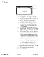
Step 9. Use the four screws included with the communications card to
attach the cart to standoffs on the host main board. Tighten the
screws to 8.0 in-lbs (0.9 Nm) to prevent stripping the threads in
the nylon standoffs.
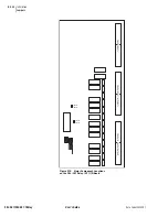
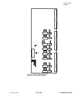
Step 10. Reinstall the SEL-421 Relay main board, and reconnect power,
interface board cables, and the input board analog cable.
Step 11. Reattach rear-panel connections. Affix the screw terminal
connectors to the appropriate 100-addresses locations on the
rear panel. Reconnect any serial cables that you removed in the
disassembly process to the EIA-232 Ports.
Step 12. Reattach the front panel.
Step 13. Follow your company standard procedure to return the relay to
service.
Step 14. Proceed with the Initial Checkout procedures for your
communications card.
Summary of Contents for SEL-421
Page 8: ...This page intentionally left blank ...
Page 30: ...This page intentionally left blank ...
Page 110: ...This page intentionally left blank ...
Page 204: ...This page intentionally left blank ...
Page 284: ...This page intentionally left blank ...

