SEL-487B Data Sheet
Schweitzer Engineering Laboratories, Inc.
8
Tie-Breaker Configurations
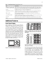
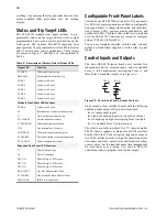
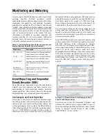
Figure 13, Figure 14, and Figure 15 show three tie-
breaker schemes:
➤
Two CTs configured in overlap (Figure 13)
➤
A single CT with two cores configured in overlap
(Figure 14)
➤
Two CTs configured with a differential element
across the breaker (Figure 15)
Configure any one of these schemes without using
external auxiliary relays. Figure 13 and Figure 14 also
show the tie breaker closing onto an existing fault, F1.
The SEL-487B includes tie-breaker logic to prevent the
loss of both zones for this fault.
T
Figure 13
Two CTs Configured in Overlap
Figure 14
A Single CT With Two CT Cores Configured in
Overlap
Configure one of the differential zones as a differential
across the tie breaker. This arrangement has the
following advantages:
➤
Both main zones are secure for a fault between the
tie breaker and the CT.
➤
Only one main zone is tripped for a fault between
the tie breaker and the CT (as opposed to both
main zones with an overlapping tie-breaker
arrangement).
Figure 15
Two CTs Configured With a Differential
Element Across the Breaker
Six Independent Settings Groups
Increase Operation Flexibility
The relay stores six settings groups. Select the active set-
tings group by control input, command, or other pro-
grammable conditions. Use these settings groups to
cover a wide range of protection and control contingen-
cies.
Selectable settings groups make the SEL-487B ideal for
applications requiring frequent settings changes and for
adapting the protection to changing system conditions.
Selecting a group also selects logic settings. Program
group logic to adjust settings for different operating
conditions, such as station maintenance, seasonal
operations, and emergency contingencies.
Applications
Figure 16 shows a station with double bus sections and a
bus tie breaker. Use a single SEL-487B for this
application.
For stations with breaker-and-a-half busbar configuration
and seven or fewer connections to either busbar, use an
SEL-487B for each busbar, as in Figure 17.
52
Bus 1
Bus 2
B1
F1
B2
Bus 1
Bus 2
B1
B2
52
F1
52
Bus 1
Bus 2
B1
B2
87


