background image

5

TPS_ED1401-ENIT

General Description

Descrizione Generale

Introduction

TPS is a complete unit range which can be equipped with SF6 

disconnector or switch disconnector and vacuum circuit breaker. 

It is suitable for switching, protection and measuring applications 

in the secondary distribution network up to 24kV. 

Modular units are adapted to future ensuring at the same time 

maximum personnel safety. 

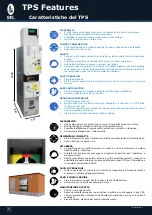
Construction Characteristics

The switchboard is made of a metal structure composed of 

galvanized steel sheets that are assembled using rivets and bolts. 

This structure is built to withstand the electrodynamic stresses 

during  the  operation.  A  switch  and  earthing  switch  are  fixed  to 

this structure. A switch envelope made of epoxy resin makes 

the isolation possible between the structure and live parts. An 

operating mechanism, a mechanical position indicator and a voltage 

indicator are positioned in the front of the unit. The position of the 

switch is given by the mechanical indicator whereas the voltage 

signalling lamp indicates the presence of voltage. Visibility of main 

contacts can be checked through an inspection window positioned 

above the operating mechanism. In the front of the unit there is 

a door giving access to different compartments, e.g. cables, fuses 

and measurement. When the unit is equipped with a low voltage 

auxiliary compartment it is situated in its upper part.

Safety

The personnel safety is obtained by means of mechanical

Interlocks as follows:

• 

When the switch is closed it cannot be earthed and the access 

to MV cables is prevented.

• 

When the switch is earthed it is impossible to close the switch 

but there is a free access to MV cables.

• 

When the access door to MV cables is opened it is impossible 

to close the switch.

Metal screens prevent access to live parts during maintenance 

operations. In addition to the functional interlocks it is possible to 

lock the switch in three positions “opened, closed, earthed” with 

the help of keylocks. 

In case of overpressure the maximum personnel safety is 

guaranteed by the opening of the safety membrane located on the 

back side of the switch. In this way the gas is directed to the back 

of the unit away from the operator.

Versions

TPS is available in the following two series:

•  Standard series: (IAC AFL 12,5kA 1s)

The series guarantees the internal arc protection on 3 sides 

up to 12,5kA for 1s.

•  Internal arc proof series: (IAC AFLR 16kA 1s)

The series guarantees the internal arc protection on 4 sides 

up to 16kA for 1 s. The robust and reinforced metal structure 

provides protection against internal arc. 

•  Internal arc proof series: (IAC AFLR 21kA 1s)

The TPS is also available in a version that guarantees the 

internal arc protection on 4 sides up to 21kA for 1 s. The 

robust and reinforced metal structure provides protection 

against internal arc. 

Presentazione

I quadri MT tipo TPS possono essere dotati di sezionatori isolati in 

gas SF6 e dove impiegati interruttori isolati in vacuum.

Impiegati su reti di distribuzione elettrica in media tensione fino a 

24kV per sezionamento, protezione e misura

Ampliabili in qualsiasi momento grazie alla modularità dimensionale 

delle singole unità, mantengono un elevato grado di affidabilità e 

di sicurezza per l’operatore.

Caratteristiche Costruttive

Il quadro è formato da una struttura metallica costituita da 

profilati,  pannelli  e  divisori  in  lamiera  d’acciaio,  uniti  fra  loro 

meccanicamente. La struttura nell’insieme è in grado di resistere 

alle sollecitazioni elettrodinamiche cui è sottoposta durante 

l’esercizio.

A tale struttura è fissato l’organo di sezionamento e messa a terra; 

l’involucro in resina di questo apparecchio permette l’isolamento 

fra la struttura e le parti attive.

Sul fronte è posizionato l’insieme degli organi di comando e 

segnalazione. Un sinottico animato permette di stabilire in maniera 

univoca la posizione del sezionatore, mentre un visualizzatore a 

tre lampade indica la presenza o meno di tensione.

E’ possibile ispezionare l’interno del sezionatore attraverso un oblò 

trasparente posizionato sopra il carter di comando.

Sempre sul fronte si trova la porta di accesso al vano cavi , fusibili, 

misure interruttore ecc.

Il vano BT per servizi ausiliari, può essere  posto in alto, oppure 

nella parte alta frontale dello scomparto.

Sicurezza

La sicurezza del personale è ottenuta con interblocchi meccanici 

atti a realizzare le seguenti funzioni:

• 

Con sezionatore chiuso su linea è impedita la manovra di 

messa a terra e l’apertura della porta di accesso al vano cavi.

• 

Con sezionatore messo a terra è impedita la chiusura su linea 

mentre è possibile aprire la porta di accesso al vano cavi.

• 

Con la porta di accesso aperta è impossibile togliere il 

sezionatore dalla posizione di terra e quindi chiuderlo su Linea.

Opportuni diaframmi metallici impediscono inoltre l’accesso alle 

parti in tensione durante gli interventi di manutenzione.

È possibile rendere fisse le 3 posizioni di funzionamento grazie ad 

opportuni blocchi a chiave.

Una valvola di sicurezza, contro eventuali sovra pressioni interne 

causate da un arco interno, è posizionata nella parte posteriore del 

sezionatore. In caso di guasto, i gas saranno espulsi verso il retro 

del quadro, senza causare danni all’operatore.

Versioni

TPS è fornito in due differenti versioni:

•  Versione Standard: (IAC AFL 12,5kA 1s)

Garantisce la tenuta al guasto interno su tre lati fino a  12,5kA 

per 1 sec.

•  Versione a tenuta d’arco interno: (IAC AFLR 16kA 1s)

Il TPS è progettato per resistere ad un guasto interno causato 

da  corto  circuito  fino  a  16kA  per  1  secondo,  prevenendo 

qualsiasi pericolo per l’operatore. La robusta struttura metallica 

del TPS previene deformazioni ed assicura la protezione in 

caso di guasto.

•  Versione a tenuta d’arco interno: (IAC AFLR 21kA 1s)

Il TPS è disponibile anche nella versione per resistere ad un 

guasto interno causato da corto circuito a 21kA per 1 secondo, 

prevenendo qualsiasi pericolo per l’operatore. La robusta 

struttura metallica del TPS previene deformazioni ed assicura 

la protezione in caso di guasto.

Summary of Contents for TPS 12kv

Page 1: ...1 TPS_ED1401 ITIN...

Page 2: ...TPS_ED1401 ENIT 2...

Page 3: ...B 2MCB 20 VTs and CTs units FIM FIM5 FIM7 FMM MTV MTVS MTA Scomparti con TA e TV FIM FIM5 FIM7 FMM MTV MTVS MTA 24 Cables and Busbars Earthing units CME ESM Scomparti per messa a terra di cavi e sbarr...

Page 4: ...e applicazioni su reti di distribuzione elettrica secondaria Power supply companies Power stations Cement industry Automotive industry Iron and steel works Windmills Solar plant Textile paper and food...

Page 5: ...lati in gas SF6 e dove impiegati interruttori isolati in vacuum Impiegati su reti di distribuzione elettrica in media tensione fino a 24kV per sezionamento protezione e misura Ampliabili in qualsiasi...

Page 6: ...tion with reduced maintenance under normal operating conditions High level of electrical endurance when breaking FLESSIBILITA Una vasta gamma di prodotti che coprono le necessit presenti e future Modu...

Page 7: ...To Failure MTTR MDT Mean Time To Repair Tutto il processo produttivo del TPS avviene seguendo lo specifico manuale del nostro sistema di qualit Il sistema di qualit stato riconosciuto da una organizz...

Page 8: ...hio ed elettrica elevate Assenza di manutenzione delle parti che eseguono il sezionamento Sicurezza e stabilit di funzionamento Dimensioni ridotte Switch disconnector The switch disconnector is made u...

Page 9: ...ora pi sicura l interfaccia operatore apparecchiatura il sezionatore dotato di due tipi di segnalazione di posizione 1 Un sinottico animato solidale ai contatti mobili dell apparecchio 2 Un obl fronta...

Page 10: ...polvere ed assicura la tenuta all impulso atmosferico sulla superficie esterna dell ampolla Vacuum technology Nowadays the interruption of current in vacuum is recognised as the dominant technology i...

Page 11: ...lto o in basso divenendo un polo interruttore passante Questa caratteristica consente di avere dimensioni del quadro estremamente ridotte e compatte e di accoppiarsi solidamente e facilmente con i pol...

Page 12: ...ura ed apertura indipendenti dall azione dell operatore consente di eseguire un ciclo O C O senza bisogno di ricaricare le molle inoltre garantisce la sequenza a ciclo rapido O 0 3s CO 3min CO permett...

Page 13: ...recenti dello standard IEC di seguito elencate IEC 62271 1 Prescrizioni comuni per l apparecchiatura di comando e di manovra ad alta tensione Temperatura ambiente Valore massimo 40 C Valore massimo d...

Page 14: ...or IEC 62271 103 100 Breaks at In p f 0 7 Class E3 Mechanical Operation Earthing Switch IEC 62271 102 1 000 Operations Class M1 Electrical Operation Earthing Switch IEC 62271 102 making capacity 5 Cla...

Page 15: ...kA 2 5 x IK Tempo di tenuta a corto circuito tK s 3 1 3 Grado di protezione sul fronte IP 3X Grado di protezione interno IP 20 Operazioni Meccaniche IMS IEC 62271 103 1 000 Manovre Classe M1 Operazio...

Page 16: ...iore circuiti ausiliari Manometer for TPS Switch Manometro per Sezionatore TPS Surge arresters Scaricatori Basic Equipment SM SM5 BSM SMS Equipaggiamento di base Switch and Earthing Switch with making...

Page 17: ...duct Canalina superiore circuiti ausiliari Surge arresters Scaricatori Voltage Indicator Spie presenza tensione Basic Equipment CM CM5 IOC BM Equipaggiamento di base Cables Holder Reggicavi Bottom pla...

Page 18: ...ra con potere di chiusura Voltage Indicator Spie presenza tensione Visibility of main contacts on switch disconnector Obl ispezione contatti principali su sezionatore Mechanical position indicator Ind...

Page 19: ...tore Auxiliary contacts on switch and earthing switch Contatti ausiliari su linea e su terra Keylocks and padlock holder Blocchi a chiave e Lucchettabilit Upper input output cables box Ingresso Uscita...

Page 20: ...ve su interruttore Aperto Optional Accessories ICB SCB Componenti Opzionali Motor for circuit breaker Motorizzazione interruttore Auxiliary contacts on switch and earthing switch Contatti ausiliari su...

Page 21: ...mponenti Opzionali Motor for circuit breaker Motorizzazione interruttore Auxiliary contacts on switch and earthing switch Contatti ausiliari su linea e su terra Keylocks and padlock holder Blocchi a c...

Page 22: ...or for circuit breaker Motorizzazione interruttore Auxiliary contacts on switch and earthing switch Contatti ausiliari su linea e su terra Keylocks and padlock holder Blocchi a chiave e Lucchettabilit...

Page 23: ...MCB Componenti Opzionali Motor for circuit breaker Motorizzazione interruttore Auxiliary contacts on switch and earthing switch Contatti ausiliari su linea e su terra Keylocks and padlock holder Blocc...

Page 24: ...bilit Upper input output cables box Ingresso Uscita cavi dall alto Base Zoccolo LV compartment for auxiliary circuits Cassonetto ausiliari BT Anti condensation heater Resistenza anticondensa Upper aux...

Page 25: ...ter Resistenza anticondensa Upper auxiliary circuits duct Canalina superiore circuiti ausiliari Fuses Fusibili Up to 3 VTs 2 VTs Phase to Phase or 3 VTs Phase to Earth Fino a 3 TV 2 TV Fase Fase o 3 T...

Page 26: ...al Accessories CME ESM Componenti Opzionali Auxiliary contacts on switch and earthing switch Contatti ausiliari su linea e su terra Keylocks and padlock holder Blocchi a chiave e Lucchettabilit Upper...

Page 27: ...ntatti ausiliari su linea e su terra Keylocks and padlock holder Blocchi a chiave e Lucchettabilit Upper input output cables box Ingresso Uscita cavi dall alto Base Zoccolo LV compartment for auxiliar...

Page 28: ...ntacts on earth switch Contatti ausiliari su sezionatore di terra N 3 Fuses 0 5A 24kV and fuses holder N 3 Fusibili 0 5A 24kV e portafusibili Cables terminal connection point Attacco cavi MBMP Meterin...

Page 29: ...Up to 3 CTs Fino a 3 TA Up to 3 VTs Fino a 3 TV N 3 Fuses 0 5A 24kV and fuses holder N 3 Fusibili 0 5A 24kV e portafusibili MBMC Metering unit with lower outgoing cables MCMP Metering unit with lower...

Page 30: ...i Standard Dati dimensionali L 375 L 500 SM SMS FIM FS BSM ESM SM5 FS5 L 500 L 750 FIM5 FSM SMM SMMR FIM7 L 750 ICB ICBR ICBLT SCB SCBR SCBLT 2ICB 2MCB L 500 L 750 CM5 CME MBER L 500 L 750 FMM MTA MBM...

Page 31: ...rno Dati dimensionali L 750 ICB ICBR ICBLT SCB SCBR SCBLT 2ICB 2MCB L 375 ICBV ILCBV L 375 L 500 SM SMS FIM FS BSM ESM SM5 FS5 L 500 L 750 CM5 CME FIM5 MBER FSM SMM SMMR FIM7 L 375 BM IOC CM MTV MTVS...

Page 32: ...no Dati dimensionali L 750 ICB ICBR ICBLT SCB SCBR SCBLT 2ICB 2MCB L 375 ICBV ILCBV L 375 L 500 SM SMS FIM FS BSM ESM SM5 FS5 L 500 L 750 CM5 CME FIM5 MBER FSM SMM SMMR FIM7 L 375 BM IOC CM MTV MTVS L...

Page 33: ...375 350 840 500 350 840 750 350 840 The use of base simplifies cable connection helps to keep the correct bending radius of the cables and reduces the trench depth in civil engineering works L utilizz...

Page 34: ...op or to the bottom of the units In the upwards exhaust version there are two possible solutions available Exhaust gases are canalized directly in the atmosphere see Fig 1 Exhaust gases are canalized...

Page 35: ...the units is used to direct the gases outside In this way the gases will loose their energy before going out through the grid doors La versione che espelle i gas combusti verso il basso utilizza il v...

Page 36: ...estrarla per impedire la chiusura della Terra E Keylock with earthing switch closed When the earthing switch is closed turn the key clockwise and remove it in order to prevent the opening of the eart...

Page 37: ...Comando LT Comando NL Comando E 3D Operating mechanism TCB Circuit Breaker unit operating mechanism Not for ILCBV For ILCBV TCB Circuit Breaker unit operating mechanism Comando 3D Comando TCB per scom...

Page 38: ...s Protection Relay Accessori Rel di protezione Protection relay installed in LV compartment Protection relay installed in LV Block compartment Esempio di rel montato in cassonetto BT Esempio di rel mo...

Page 39: ...pi complesso non lo permettono i rel ed i circuiti ausiliari saranno alloggiati in apposito cassonetto BT posizionato sopra o sul fronte del quadro The LV compartment can be installed on the roof or...

Page 40: ...5 Fig 6 Fig 7 Fig 8 Lateral Input Output Cables Ingresso Uscita cavi Laterale Fig 6 7 Lateral input cables from CM unit Fig 8 Lateral Outgoing cable system from ICBV ILCBV to transformer Fig 6 7 Soluz...

Page 41: ...ristiche elettriche Discharge rated current 10 kA Corrente nominale di scarica Rated voltage 3 33 kV Tensione nominale Discharge max current 100 kA Corrente massima di scarica Discharge current for 2...

Page 42: ...per protezione trasformatori Per la scelta dei fusibili necessario conoscere alcune importanti caratteristiche del trasformatore e confrontarle con quelle del fusibile Trasformatore Potenza nominale P...

Page 43: ...25 31 5 40 50 63 80 100 125 23 24 6 6 10 10 16 16 20 25 31 5 40 50 63 80 100 33 36 4 6 6 10 10 10 16 20 25 31 5 40 40 50 63 36 36 4 6 6 10 10 10 16 16 20 25 31 5 40 50 63 Standard fuses Fusibili stand...

Page 44: ...f powered protection relay Sganciatore di apertura a bassa energia fornito di serie con rel autoalimentati Spring charging motor optional Motore carica molle per interruttore opzionale Other Accessori...

Page 45: ...ng knob no 2 signalling lamps Two pole circuit breaker for auxiliary protection Withdrawable two pole fuse holder base for auxiliary protection Withdrawable three pole fuse holder base for secondary V...

Page 46: ...di servizio per esempio commutando automaticamente sulla linea di riserva alla mancanza delle rete elettrica principale Per il sistema ACO necessario un segnale di presenza tensione da ogni modulo di...

Page 47: ...s with LT operating mechanism Sistema di scambio automatico ACO tra due 2 IMS con comando LT Mechanical interlock between two switch disconnectors with LT operating mechanism Interblocco meccanico fra...

Page 48: ...ting degree 40 Grado Isolamento 40 mm Single core Unipolare 25 290 320 360 35 300 340 360 390 50 320 350 380 410 70 340 380 400 440 95 370 400 430 460 120 390 420 450 480 150 400 440 470 500 185 430 4...

Page 49: ...li scomparti al pavimento tramite tasselli ad espansione utilizzando la foratura indicata SM FS IOC CM SM FS IOC CM ICBV ILCBV ICBV ILCBV SM5 FS5 CM5 CME SM5 FS5 CM5 CME FSM SMM MBMC FSM SMM MBMC ICB...

Page 50: ...ximum 2 cables for phase 240 mm Massimo 2 cavi fase da 240 mm H6 470 Maximum 1 cable for phase 120 mm Massimo 1 cavi fase da 120 mm H7 470 Maximum 2 cables for phase 120 mm Massimo 2 cavi fase da 120...

Page 51: ...51 TPS_ED1401 ENIT Download our PDF Catalog Scarica il nostro Catalogo in PDF 10 04 14...

Page 52: ...TPS_ED1401 ITIN 52...

Reviews: