22
17.7 Luff extrusion system
For a better understanding of the following instructions, we recommend that you first read the section
on assembly in chapter 4.1.
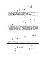
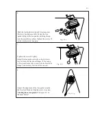
1. Place the luff extrusions on a flat surface, and make sure that they are straight.
2. Remove the eye part of the upper terminal
3 Knock out the locking pin at 800 mm (200TD) / 770 mm (300TD) / 660 mm (400TD) extrusions
lower end.
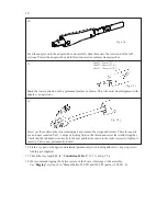
4. Hold the luff extrusion system firmly and pull the lower terminal. This will bring the rod forestay, joi-
ning sleeves and distance tubes out together.
If this method does not work due to corrosion or damage, the luff extrusion system connectors can
be drilled out. Use a Ø 6 mm (15/64") drill bit for the 200 TD, Ø 8 mm for 300 TD, and 400 TD.
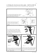
17.8 Top guard
If exchanging the top guard:
Navtec -12/200 S, -22, -30, -40 and Rigging -40, -48:
The top guard cannot be removed from the sys-
tem by sliding them over the top eye terminal unless the eye part of the terminal is removed first.
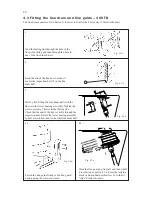
Navatec -48, Rigging -22 mm:
The internal flange at the top edge of the guard needs to be filed down.
Alternatively, the guard can be removed from below when dismantling the sail feeder and removing
the lower bearing assembly and halyard swivel.
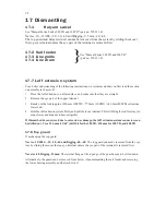
17 Dismantling
17.1
Halyard swivel
See "Manual Furlex Furlex 200 TD and 300 TD" (part no: 595-231-E).
Navtec -10, -12/200, -22, -30, -40 and Rigging -9.5 mm, -40, -48.
The top guard and halyard swivel cannot be removed from the system by sliding them over
the top eye terminal unless the eye part of the terminal is removed first.
17.2 Sail feeder
17.3 Line guide
17.4 Line drum
See "Manual Furlex 200 TD and 300 TD"
(part no: 595-231-E)
}
Summary of Contents for Furlex 200 TD
Page 23: ...23 Notes Comments...

