11
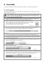
1.
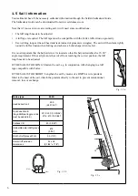
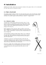
Stretch out the wire on a flat, clean surface. On stays with swaged lower terminal, be careful not to
damage the terminal thread. The thread can be protected with tape or similar.
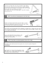
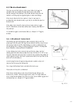
2. Start by feeding the top luff extrusion and the top distance tube onto the forestay wire.
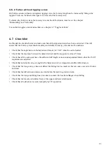
Make sure that the cut end of the top luff extrusion is up (hole down). with distance
tubes are welded shut but are easily opened by hand. Note the correct
orientation of the distance tube - hinge to be sideways.
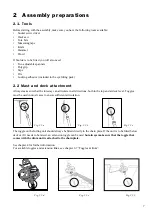
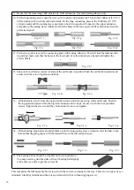
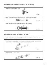
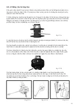
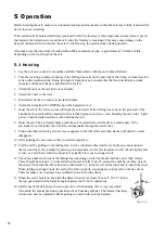
3. Add a short joining sleeve and use it to push the distance tube up into the top luff extrusion. The
distance tube should be pushed in approximately half the length of a joining sleeve.
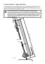
4.
On Sta-lok terminated systems, the halyard swivel and the top guard can be fitted at this point, see
below. On stud terminated systems, the top guard must be fitted after the sail feeder has been mounted.
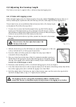
5. Add another luff extrusion and another distance tube. Make sure the distance tube is oriented correctly.
Also add another short joining sleeve.
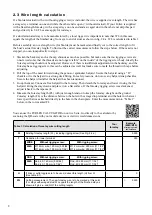
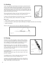
6.
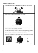
Fit a short connecting plate into the second luff extrusion as shown. Push the first joining sleeve down
into the second luff extrusion to lock the connector.
7. Connect the two luff extrusions.
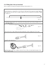
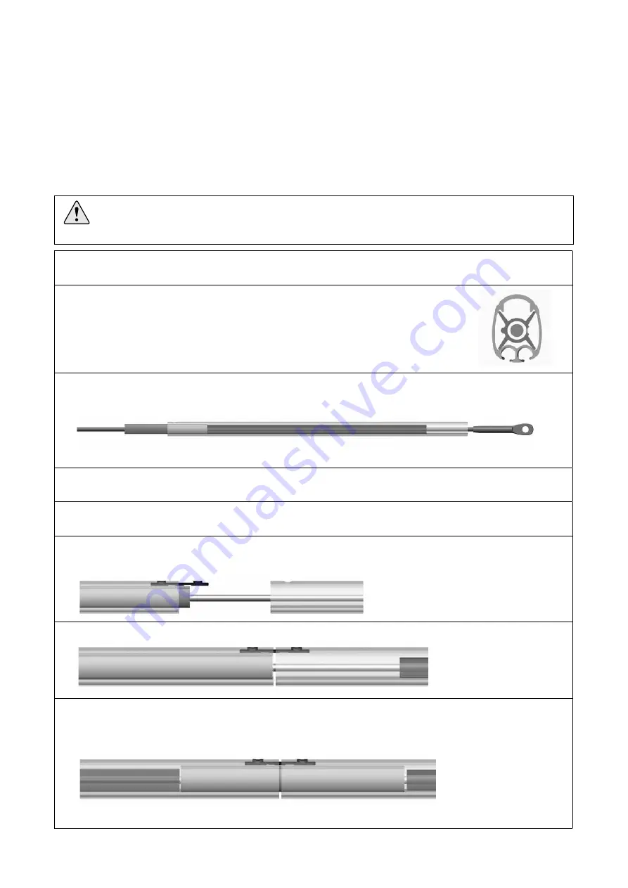
8.
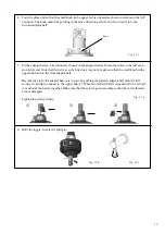
Push the first joining sleeve back up into the first luff extrusion to lock the join. Use the second joining
sleeve to push on the second distance tube. The second distance tube should be pushed in approximately
half the length of a joining sleeve. This will ensure correct location of the first joining sleeve.
3 Assembly
3.1 Luff assembly
Luff assembly should be carried out on a clean, flat surface. Make sure there is enough space for the entire
forestay length to be stretched out.
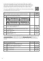
At this point the top luff section and the top distance tube should be cut to length according to table 2.
Note that the luff extrusions are fitted onto the wire, whereas on previous models the wire was
fitted as a last step. Also note that the luff is assembled from top down as opposed to older
Furlex systems, see instruction 597-184-E.
Fig. 3.1.a
Fig. 3.1.c
Fig. 3.1.d
Fig. 3.1.e
Fig. 3.1.b


