12
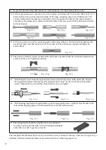
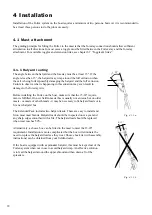
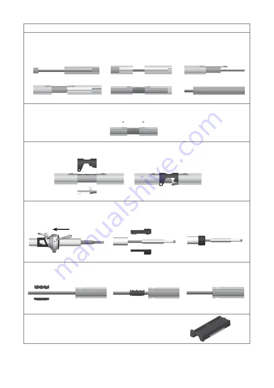
9. Repeat for the remaining 2400 mm
(94 1/2”)
luff extrusions. Use short joining sleeves only.
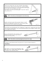
10. Fit the long joining sleeve onto the wire with two-hole end downwards. Then fit the 1000 mm (39 3/8”)
luff extrusion with two-hole end downwards. Fit the long connecting plate to the 1000 mm (39 3/8”)
extrusion and push the joining sleeve upwards to hold it in position. Connect to the upper extrusion
and push up the joining sleeve. Make sure that the holes in the lower part of luff extrusion and join are
perfectly aligned.
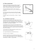
11. Fit the two grub screws in the connecting plate with locking adhesive. This will lock the distance tube
in position. make sure that the holes in the lower part of extrusion/join are aligned and tighten the
screws firmly.
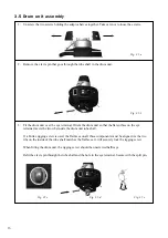
12. Snap on the sail feeder connector and put the sail feeder in position. Push the sail fedder upwards and
secure with the screw. Tighten moderately.
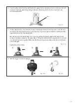
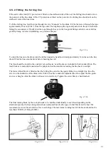
13. Fit the halyard swivel from the top and slide it down until it stops on top of the sail feeder. Then fit
the top guard and push it into the top luff extrusion until it stops. Secure it with the four pre-fitted
screws. Tighten the screws until they bottom, but do not over-tighten.
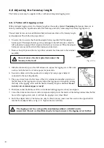
14. Fit the bearing plug halves and push them up ito the long joining sleeve. Adjust so that the hole in the
forward bearing plug aligns with the forward hole in the luff extrusion/join.
15. The bearing halves should be a tight fit in the join extrusion.
You may need to grind the sides of the aft bearing half slightly
with a file or a knife to get the correct fit.
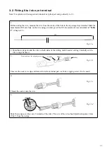
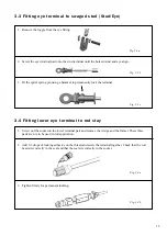
This completes the luff assembly. Next step is to fit the lower eye teminal to the stay. There are two types of eye
terminals; Stud/Eye terminal and Sta-lok eye terminal (with or without rigging screw).
Fig. 3.1.n
Fig. 3.1.m
Fig. 3.1.l
Fig. 3.1.o
Fig. 3.1.r
Fig. 3.1.p
Fig. 3.1.s
Fig. 3.1.q
Fig. 3.1.t
Fig. 3.1.f
Fig. 3.1.i
Fig. 3.1.g
Fig. 3.1.j
Fig. 3.1.h
Fig. 3.1.k


