22
4.6 Adjusting the forestay length
4.6.1 Furlex with rigging screw
The Furlex system may be supplied with or without an integrated rigging screw.
With an integral rigging screw, the forestay length can be easily adjusted.
Tensioning
the forestay however, is
done by tensioning the cap shrouds and/or the backstay, and not by tensioning the forestay rigging screw.
The sail must be removed or unfurled and halyard slackened before the forestay length
can be adjusted. Then follow the steps below:
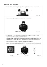
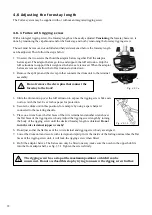
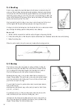
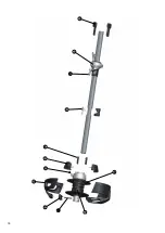
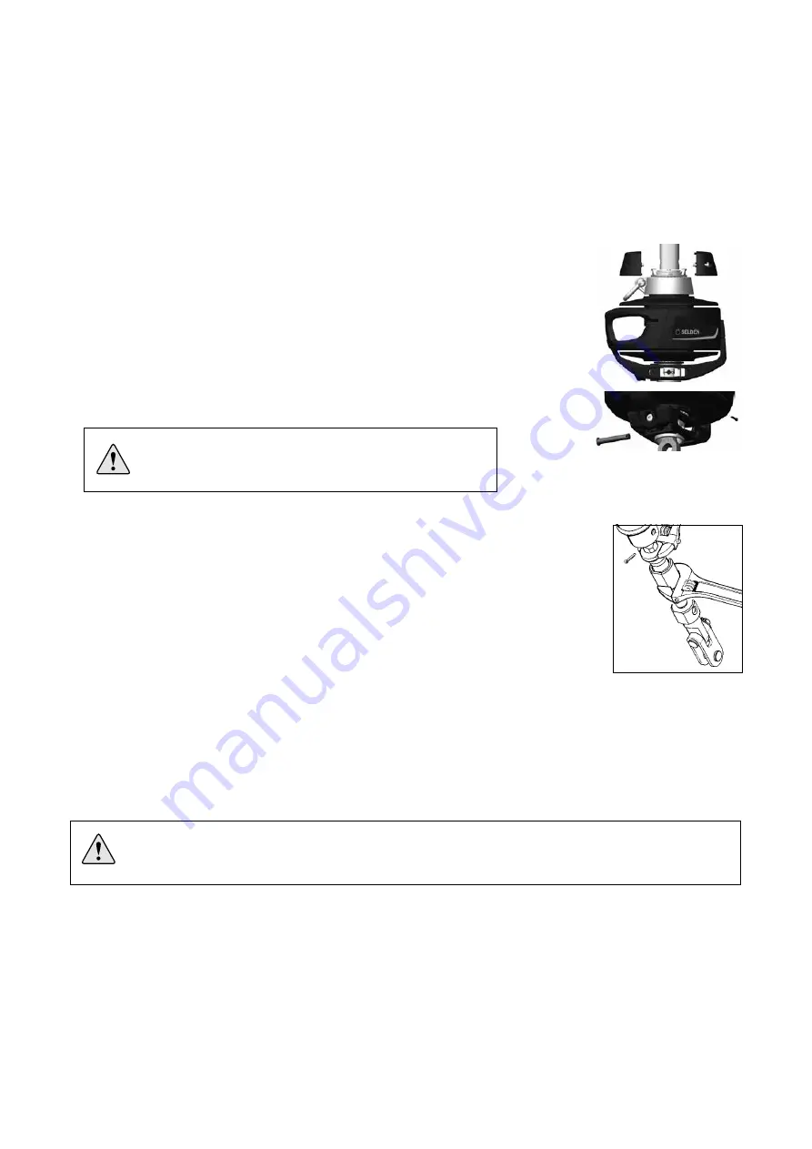
1. Unscrew the two screws that hold the adaptor halves together. Pull the adaptor
halves apart. The adaptor halves go into, and support, the luff extrusion. Grip the
luff extrusions to support their weight as the halves are removed. When the adaptor
halves are removed, allow the luff extrusions to slide down.
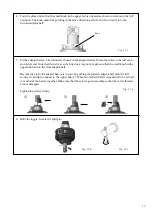
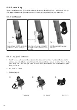
2.
Remove the split pin and the clevis pin that connects the drum unit to the terminal
assembly.
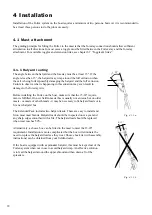
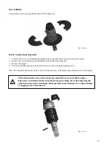
3. Slide the drum unit up over the luff extrusion to expose the rigging screw. Take care
not to scratch the foil. Use cloth or paper for protection.
4. Secure the drum unit in this position, for example by using a spare halyard
connected to the tack ring shackle.
5.
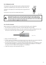
Place one wrench over the flat faces of the wire terminal and another wrench over
the flat faces of the rigging screw body. Adjust the rigging screw length by turning
the body of the rigging screw until the desired forestay length is obtained.
Do not
turn the wire terminal (upper wrench)!
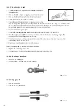
6.
Re-adjust so that the flat faces of the wire terminal and rigging screw body are aligned.
7.
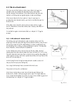
Lower the drum unit and secure with clevispin and split pin. As the inside of the furling unit matches the flat
faces of the rigging screw unit, it will lock the rigging screw when fitted.
8.
Re-fit the adaptor halves. The halves can only be fitted one way; make sure the notch in the upper hub fits
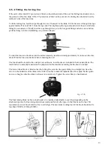
into the front adaptor half, see fig. 3.5.f. Tighten the screws firmly.
Do not remove the clevis pins that connect the
forestay to the boat!
The rigging screw has a stop at the maximum position to which it can be
unscrewed. Do not overload this stop by trying to unscrew the rigging screw further.
Fig. 4.6.1.a
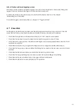
Fig. 4.6.1.b

