26
5.4 Reefing
5.5 Racing
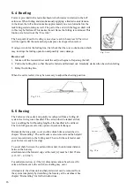
Furlex is provided with a tack attachment which rotates in relation to the luff
extrusion. When furling and simultaneously applying a limited countertension
in the sheet, the luff extrusion makes approximately one revolution before the
tack fitting starts rotating as well. The part of the sail with the biggest draft will
in this way be flattened. This makes the sail flat as the furling is continued. This
funtion is referred to as the ”Free turn”.
The best point of sail for reefing is on a close reach to beam reach. The wind
will then partly fill the sail and help to improve its shape when reefed.
If using a winch for the furling line, first check that there is no obstruction which
may interrupt the furling operation and possibly cause damage.
How to reef:
1.
Slacken off the leeward sheet until the sail just begins to flap along the luff.
2.
Pull in the furling line so that the sail is furled and flattened out. Gradually slacken the sheet when furling.
3. Belay the furling line.
When the sail is reefed, it may be necessary to adjust the sheeting position.
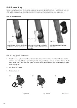
The Furlex can be easily and quickly reconfigured from a furling jib
system to a twin-groove headfoil. The sail can then be tacked at deck
level, enabling the full hoisting length of the headfoil to be utilized.
The twin luff grooves offer the option of quick sail changes.
Dismantle the line guide, cover and line drum brims as described in
chapter ”Dismantling”. The sail feeder is also removed and the halyard
swivel moved down to the furling unit. Then re-fit the sail feeder and
your Furlex is ready for racing!
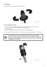
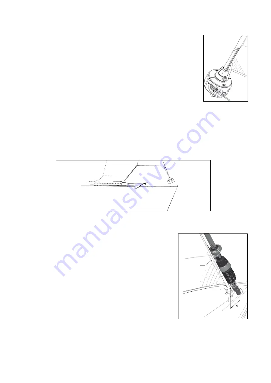
To avoid chafe between the sail and drum unit, the minimum distance
between the forestay
attachment and the forward edge of the tack [A] must be 100-125 mm
(3 15/16” - 4 59/64”).
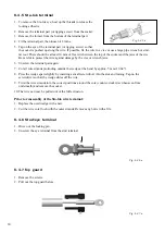
For added protection, or if the [A] dimension cannot be achieved, fit
extra reinforcement to the sail where chafing may occur.
Alternatively, the drum unit and halyard swivel can be removed from
the system completely by detatching the forestay at the stemhead. See
chapter ”Dismantling” for further instructions.
Protection
Fig. 5.4.a
Fig. 5.5.b
Fig. 5.5.a

