User Manual
96
User Manual
97
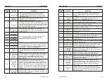
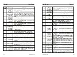
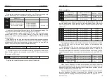
P4-12
P4-12 terminal
UP/DOWN change rate
0.001Hz/s
〜
65.535Hz/s Default
:
1.00Hz/s
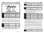
As shown in the above figure, in the control mode, when the SB1 button is
closed, press the SB2 button to run the inverter, K disconnects the inverter
from forward rotation, K closes the inverter to reverse; when the SB1 button is
disconnected, the inverter stops. During normal start-up and operation, the
SB1 button must be closed and the SB2 button command will take effect at
the end of the closing action.
It is used to set the speed at which the terminal UP/DOWN changes when
the set frequency is adjusted, that is, the amount of change in frequency per
second.
When P0-22 (frequency point) is 2, the value ranges from 0.001 Hz/s to
65.535 Hz/s.
When P0-22 (frequency decimal point) is 1, the value ranges from 0.01
Hz/s to 655.35 Hz/s.
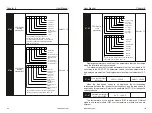
P4-13
AI curve 1 minimum
input
0.00V
〜
P4-15
Default
:
0.00V
P4-14
AI curve 1 minimum input
corresponding value
-100.0%
〜
+100.0%
Default
:
0.0%
P4-15
AI curve 1 maximum
input
P4-13
〜
+10.00V
Default
:
10.00V
P4-16
AI curve 1 maximum input
corresponding value
-100.0%
〜
+100.0%
Default
:
100.0%
P4-17
AI1 filtering time
0.00s
〜
10.00s
Default
:
0.10s
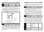
AI1 input filtering time is used to set the software filtering time of AI1.
When the field analog quantity is easily disturbed, please increase the
filtering time so that the detected analog quantity tends to be stable, but the
larger the filtering time is, the analog quantity detection is. The slower the
response.
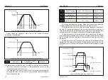
In different applications, the nominal value corresponding to 100.0% of
the analog setting is different. For details, please refer to the description of
each part. The following illustrations are for two typical settings:
When the analog input is a current input, the 1mA current is equivalent to
0.5V.
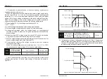
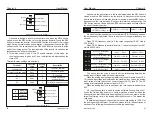
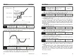
The above function code is used to set the relationship between the
analog input voltage and the set value it represents.
When the analog input voltage is greater than the set maximum input (P4-
15), the analog voltage is calculated as the maximum input; when the analog
input voltage is less than the set minimum input (P4-13), then P4 The -34
setting is calculated with a minimum input or 0.0%.
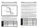
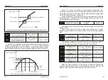
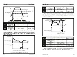
As shown in the figure above, in the control mode, when the SB1 button is
closed, press the SB2 button to turn the inverter forward. Press the SB3
button to reverse the inverter. When the SB1 button is turned off, the inverter
stops. During normal start-up and operation, it is necessary to keep the SB1
button closed. The commands of the SB2 and SB3 buttons are valid at the
end of the closing action. The running status of the inverter is based on the
last button action of the three buttons.
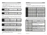
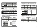
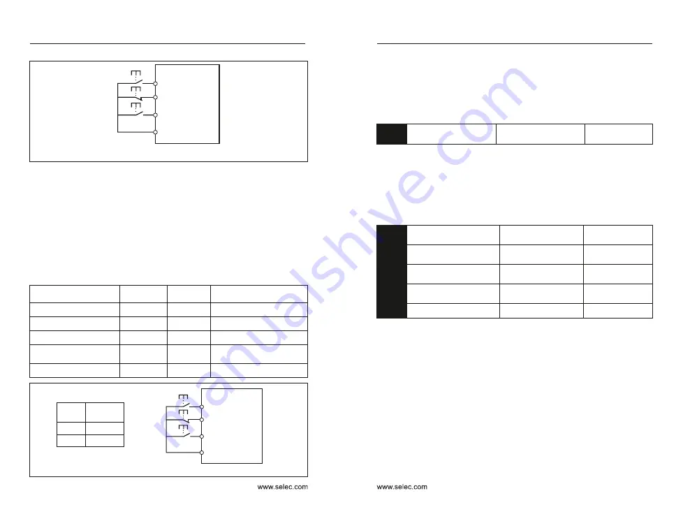
3 : Three-wire control mode 2, the X3 enable terminal of this mode, the
running command is given by X1, and the direction is determined by the
state of X2.
Terminal function settings are as follows
:
X1 Running (Open)
X3 Stop (Closed)
X2 Running direction
SB1
SB2
K
Running
Stop
COM
Figure 6-11 Three-wire control mode 2
K
0
Running
direction
1
Forward
Reverse
Chapter 6
Chapter 6
Terminal
Function
code
Setting
value
Description
Terminal command mode
P4-11
3
Three-wire type 2
X1
P4-00
1
Run enable
X2
P4-01
2
Positive & negative
running direction
X3
P4-02
3
Three-wire operation control
Control mode
P0-02
1
Control by terminal
X1 Run (Open)
X3 stop (Closed)
X2 Reverse (Open)
SB1
SB2
SB3
Forward
Stop
Reverse
COM
Figure 6-10 Three-wire control mode 1


